Interconnect pattern for high performance interfaces

Active Publication Date: 2011-08-11
ALTERA CORP
View PDF4 Cites 12 Cited by
  • Summary
  • Abstract
  • Description
  • Claims
  • Application Information

AI Technical Summary

Benefits of technology

[0005]The present invention is directed to interconnect patte

Problems solved by technology

As discussed below in conjunction with FIG. 4, the performance of an interconnection pattern such as that of FIG. 1 is not opt

Method used


Image

  • Interconnect pattern for high performance interfaces
  • Interconnect pattern for high performance interfaces
  • Interconnect pattern for high performance interfaces

Examples


Embodiment Construction

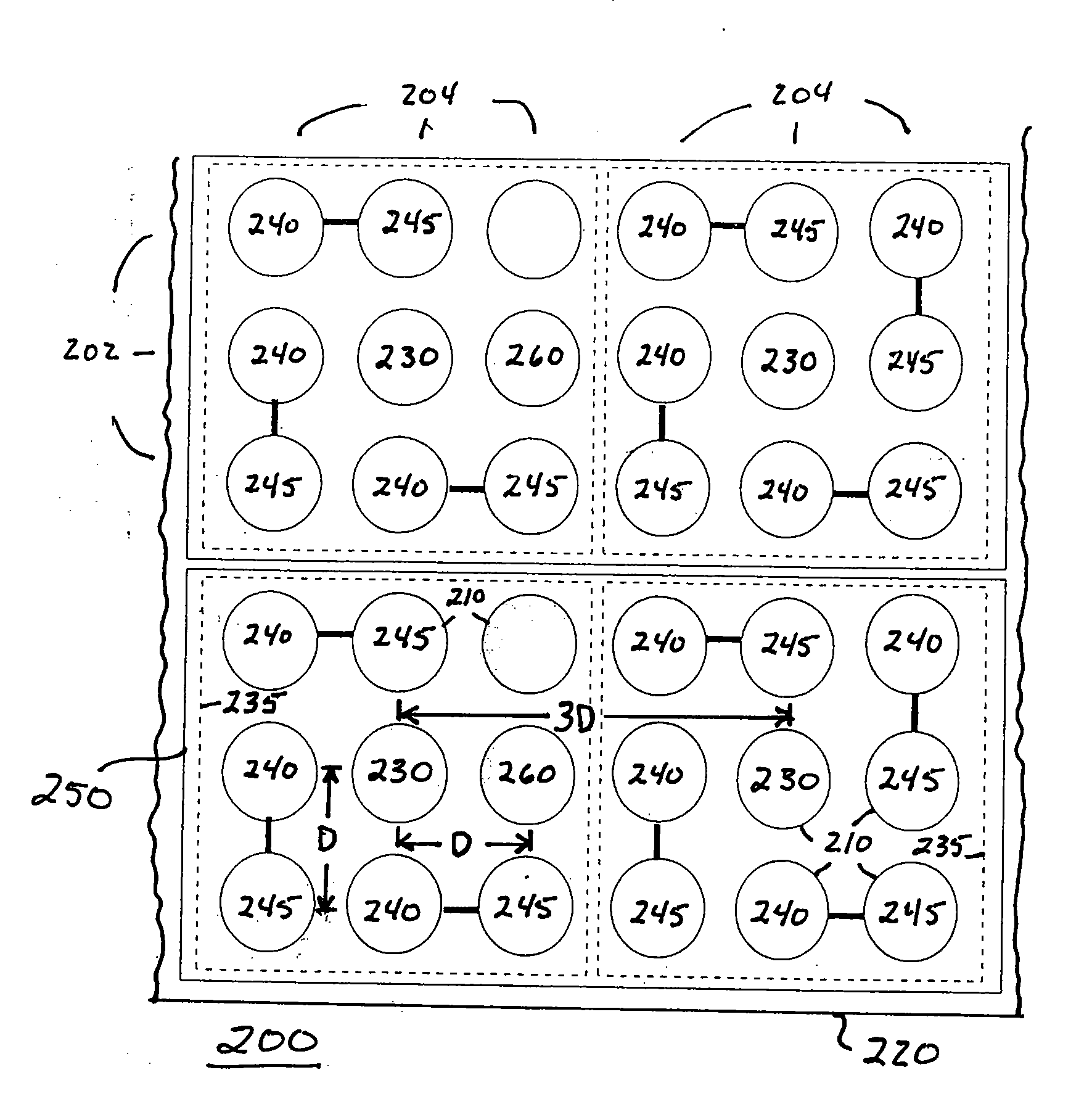
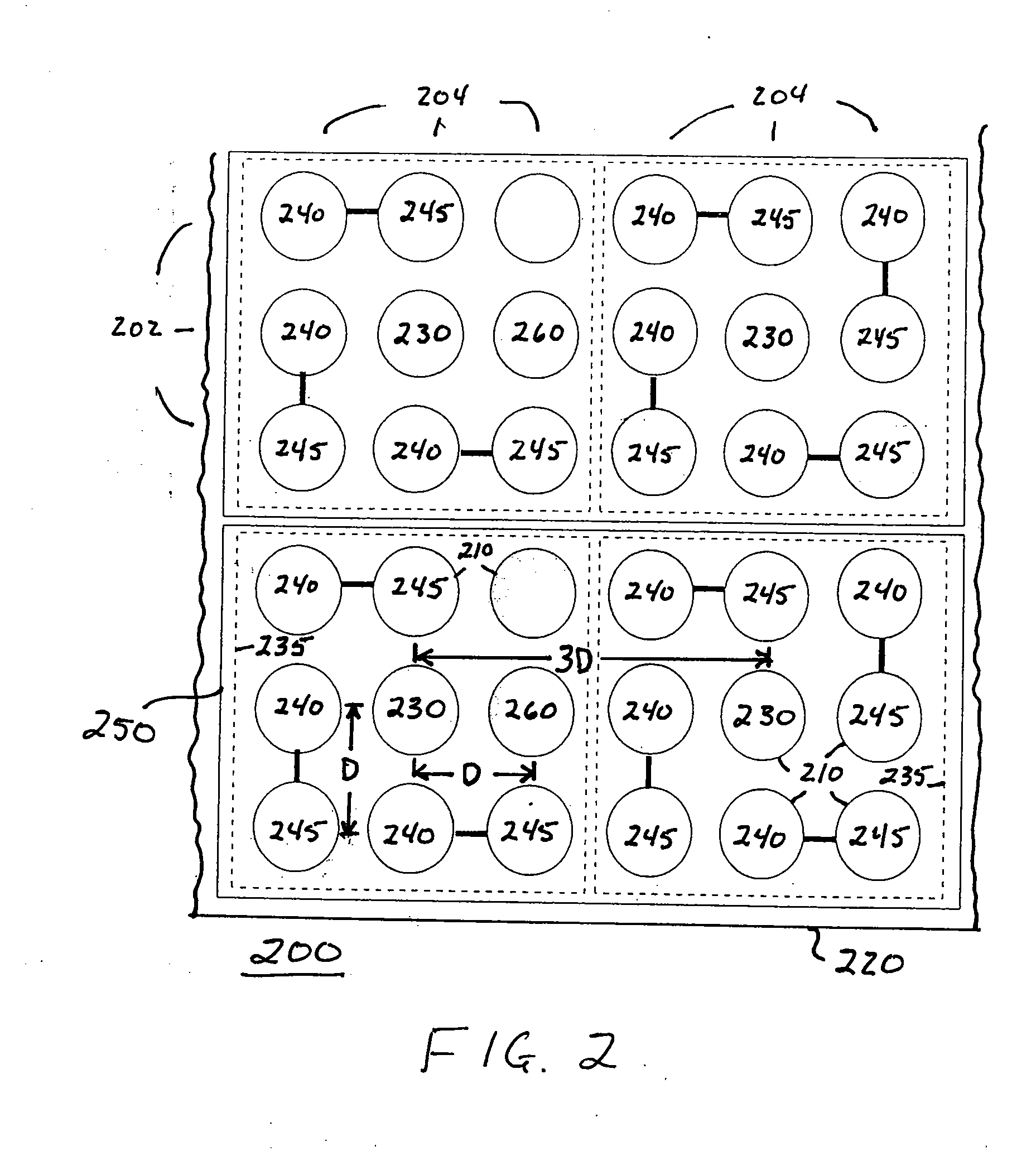
[0012]FIG. 2 depicts a rectilinear array 200 of rows 202 and columns 204 of contact sites 210 on a substrate 220 wherein adjacent rows and adjacent columns are each spaced apart by a distance D, which is commonly referred to as the pitch. A plurality of ground contacts 230 are located at certain of the contact sites 210 spaced apart by the distance 3D or three pitch distances. A plurality of pairs of differential contacts 240, 245 are located at other contact sites 210 with the contacts of each pair being located one pitch distance D from each other. Each pair of differential contacts is identified by a solid line extending between the pair of contacts 240, 245. One contact 240 of each pair is located in the array one pitch distance D away from a ground contact 230 and the other contact 245 of the pair is located approximately sqrt(2)*D away from the same ground contact 230. With this arrangement, both contacts of each differential pair are in the 3×3 array 235 of contacts centered ...


PUM


Abstract

In one embodiment, differential signaling and ground contacts are located in a rectilinear array of rows and columns with ground contacts spaced apart by three times the pitch distance between adjacent rows or columns and signaling contacts are located immediately adjacent the ground contacts. In particular, the two contacts of each differential pair are located one pitch distance apart from each other and one contact of each differential pair of contacts is located one pitch distance from a ground contact and the other contact of the differential pair is located approximately sqrt(2)*pitch distance from the same ground contact. In a second embodiment, differential signaling and ground contacts are located in a hexagonal array with ground contacts located three times the pitch distance between adjacent contacts and signaling contacts located immediately adjacent the ground contacts. In particular, the two contacts of each differential pair are located one pitch distance apart from each other and both contacts of each differential pair of contacts are located one pitch distance from a ground contact.

Description

BACKGROUND OF THE INVENTION[0001]This relates to package design and more particularly to patterns of electrical interconnects that are used for high performance devices such as high speed differential signaling transceiver pairs and memory interfaces. As is known in the art, such interfaces are typically implemented using a ball grid array (BGA) or a pin grid array (PGA). A BGA is an area array of solder balls or solder bumps that is located on the surface of a package. A PGA is an area array of pins underneath a package surface. The BGA or PGA is used to connect the package to the next level of package. See, R. R. Tummala, Fundamentals of Microsystems Packaging, pp. 67, 68, 279-281, 680-682, 925 (McGraw-Hill, 2001), which is incorporated by reference herein in its entirety. For convenience, the terms “contacts” or “interconnects” will be used hereafter to refer to solder balls, solder bumps, and interconnect pins as well as similar connectors[0002]In designing high speed differenti...

Claims


Application Information

Patent Timeline
IPC IPC(8): H01R12/04
CPCH01L23/49838H01L23/50H01L2223/6638H01L2924/3011H01R12/7082H01L2924/0002H01R13/6471H01L2924/00
Inventor LIU, HUI
Owner ALTERA CORP
Why Eureka
Try Eureka