Wireless energy transmission structure

a transmission structure and wireless technology, applied in the direction of transmission, transformer, inductance, etc., can solve the problems of low power transmission efficiency, limited use of batteries, and communication information devices still dependent on batteries, so as to improve transmission distance and transmission efficiency, and reduce the size

Active Publication Date: 2011-08-11
WITS CO LTD +1
View PDF9 Cites 3 Cited by
  • Summary
  • Abstract
  • Description
  • Claims
  • Application Information

AI Technical Summary

Benefits of technology

[0017]Accordingly, the present invention has been made keeping in mind the problems encountered in the related art and the present invention is intended to provide a

Problems solved by technology

However, communication information devices are still dependent on batteries, and the use thereof is limited because it is supplied with power by means of a wire power cable.
The microwave receiving method is advantageous because microwaves are radiated through the air by an antenna so that power can be transmitted over a distance, but is limited in that the power transmission efficiency is low attributable to a very large radiation loss in the air.
However, the magnetic induction method is problematic in that the transmission-side primary coil and the receiving-side secondary c

Method used


Image

  • Wireless energy transmission structure
  • Wireless energy transmission structure
  • Wireless energy transmission structure

Examples


first embodiment

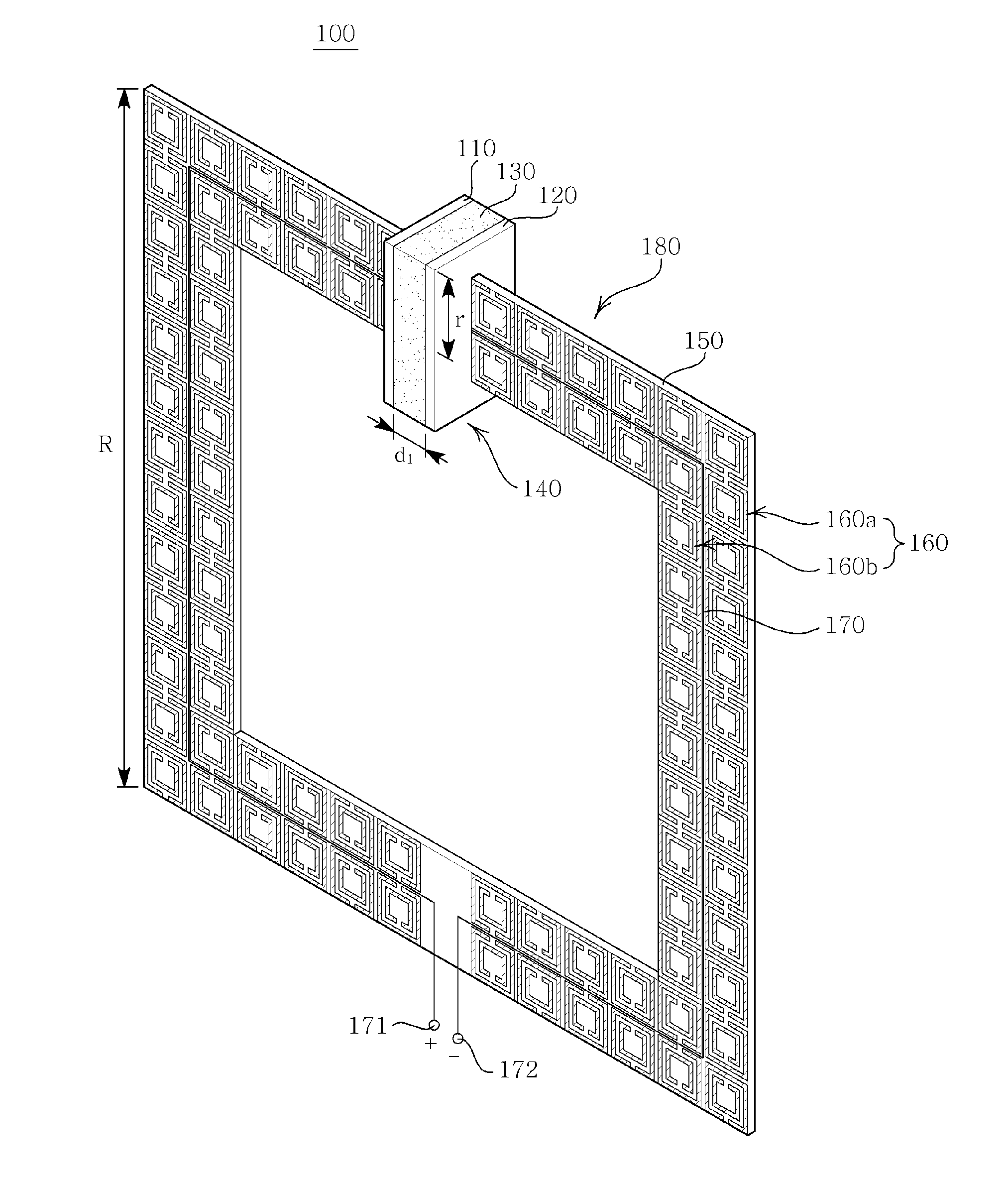
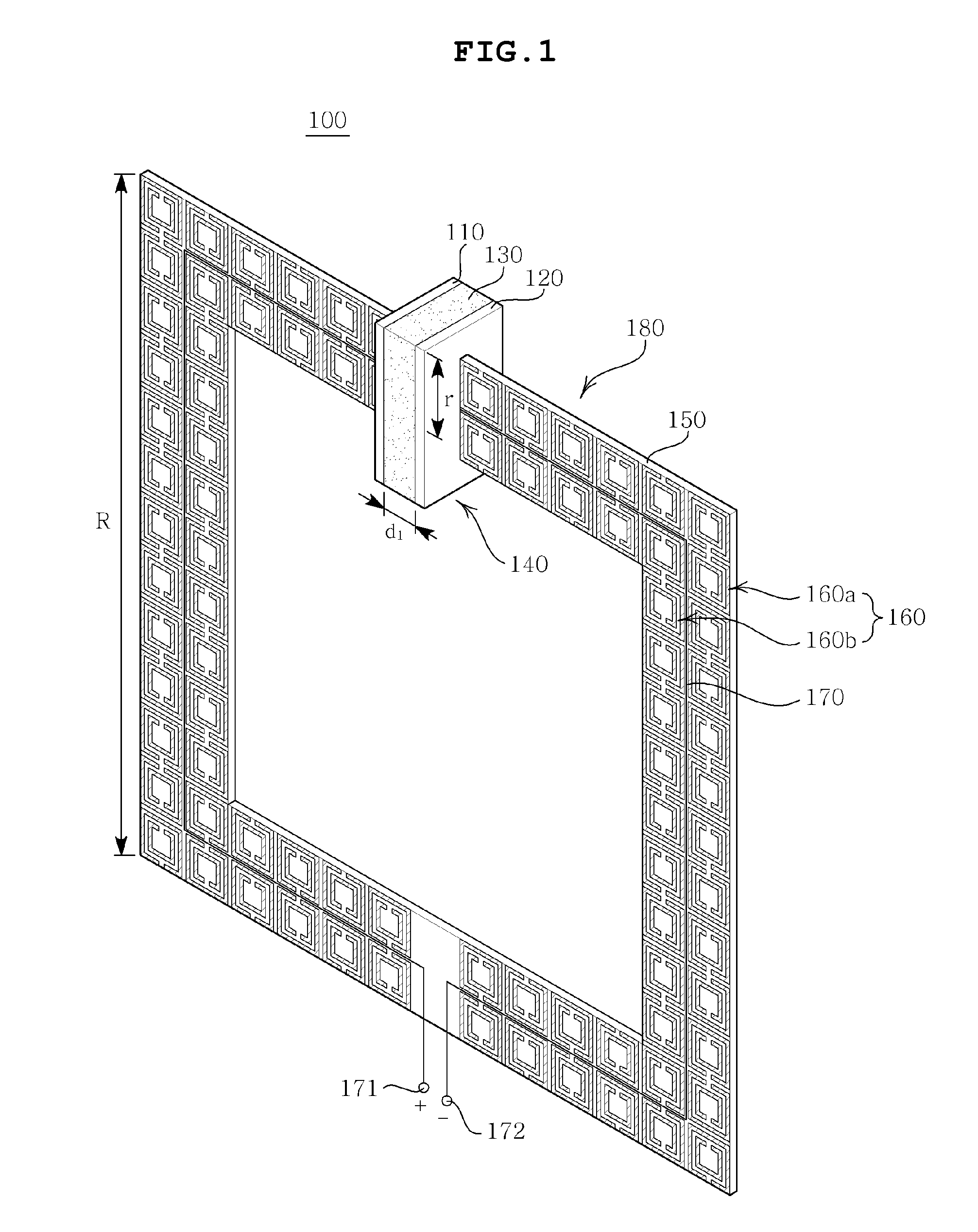
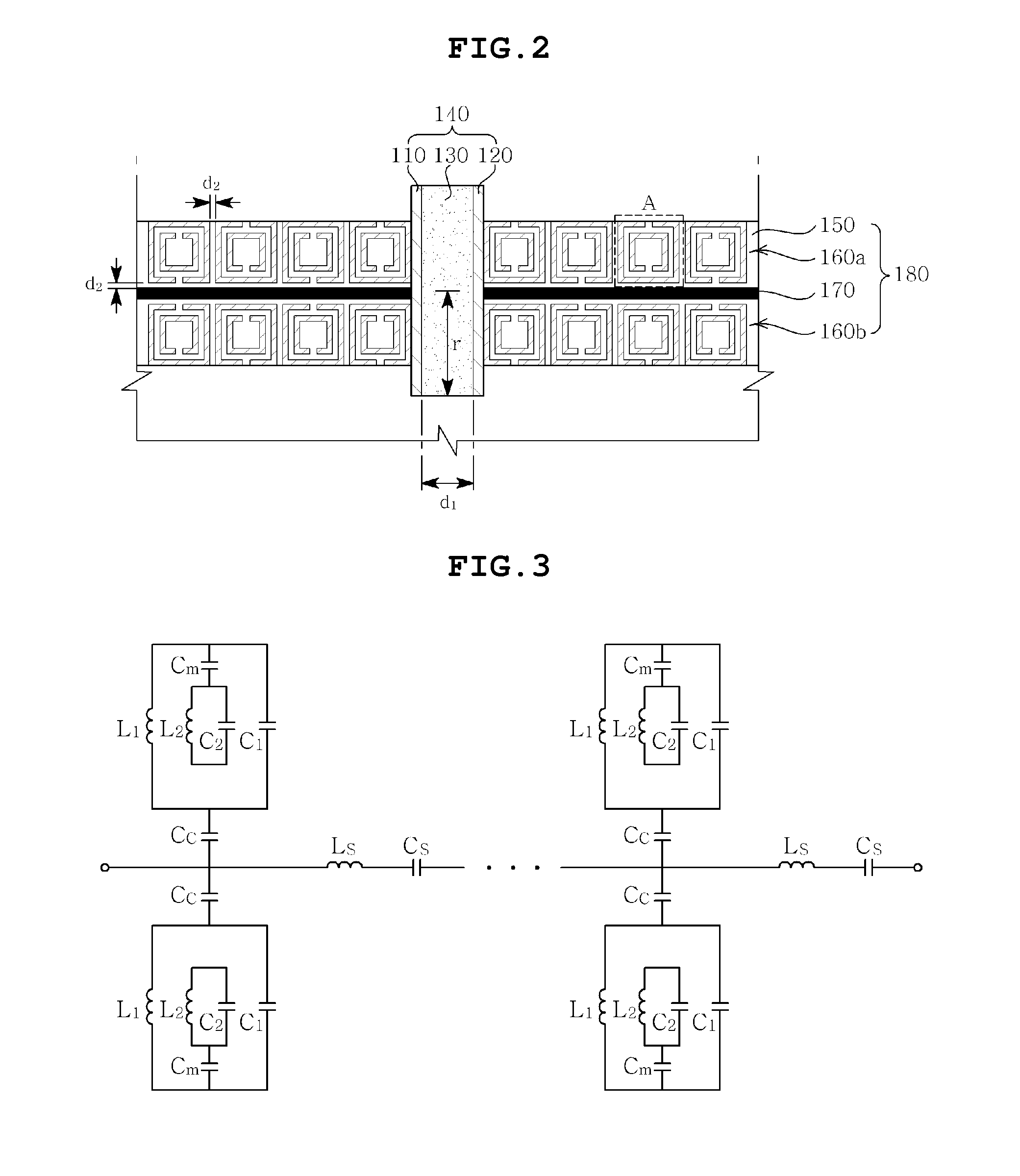
[0036]FIG. 1 is a perspective view showing a wireless energy transmission structure according to the present invention, and FIG. 2 is an expanded view of part of FIG. 1.

[0037]With reference to FIG. 1, the wireless energy transmission structure 100 according to the first embodiment of the present invention includes a disc part 140 including first and second conductor plates spaced apart from each other at a predetermined distance and a dielectric material inserted between the two conductor plates, and a ring-shaped wire part 180 connected to both ends of the disc part 140 and having a plurality of meta cells which are repetitively formed.

[0038]The disc part 140 functions as a capacitor C in LC resonance based on a magnetic field, and may include the first and second conductor plates 110, 120 spaced to face each other and the dielectric material 130 inserted between the first and second conductor plates 110, 120. When power is applied, an electric field is generated between the first ...

second embodiment

[0068]FIG. 6 is a perspective view showing a wireless energy transmission structure according to the present invention, and FIG. 7 is a cross-sectional view taken along the line A-A′ of FIG. 6.

[0069]With reference to FIG. 6, the wireless energy transmission structure 200 according to the second embodiment of the present invention includes a disc part 240 including first and second conductor plates spaced apart from each other at a predetermined distance and a dielectric material inserted between the two conductor plates, and a ring-shaped wire part 290 connected to both ends of the disc part 240 and having a plurality of meta cells which are repetitively formed.

[0070]The disc part 240 of the wireless energy transmission structure 200 according to the second embodiment of the present invention is the same as the disc part 140 of the wireless energy transmission structure 100 according to the first embodiment of the present invention, and thus the detailed description thereof is omitt...


PUM


Abstract

Disclosed is a wireless energy transmission structure which includes a disc part including a first conductor plate and a second conductor plate which are spaced to face each other and a dielectric material inserted between the first conductor plate and the second conductor plate, and generating an electric field between the first conductor plate and the second conductor plate; and a ring-shaped wire part one end of which is connected to the first conductor plate and the other end of which is connected to the second conductor plate, and having a meta structure in which a plurality of meta cells is repetitively arranged so as to induce a magnetic field using the electric field, so that the wireless energy transmission structure is reduced in size and is improved in transmission distance and transmission efficiency.

Description

CROSS REFERENCE TO RELATED APPLICATION[0001]This application claims the benefit of Korean Patent Application No. 10-2010-0011582, filed Feb. 8, 2010, entitled “Wireless energy transmission structure”, which is hereby incorporated by reference in its entirety into this application.BACKGROUND OF THE INVENTION[0002]1. Technical Field[0003]The present invention relates to a wireless energy transmission structure.[0004]2. Description of the Related Art[0005]The advancement of wireless communication technology has resulted in an environment of ubiquitous information where anyone may send and receive the desired information at any time and anywhere.[0006]However, communication information devices are still dependent on batteries, and the use thereof is limited because it is supplied with power by means of a wire power cable.[0007]In order to solve these problems, numerous techniques for wirelessly transferring power are being developed.[0008]For example, a microwave receiving method using ...

Claims


Application Information

Patent Timeline
IPC IPC(8): H01F38/14
CPCH02J5/005H04B5/0093H04B5/0037H02J50/005H02J50/12
Inventor CHOI, JAE WONSEO, CHUL HUNLEE, CHONG MINJUNG, DU WONKIM, YANG HYUNKIM, JU EUNGLEE, KWANG DUYOON, JUNG HOKIM, JEONG HOONHWANG, SANG HOONPARK, CHUL GYUNLEE, JUNG AUN
Owner WITS CO LTD
Why Eureka
Try Eureka