Electronic scanning radar apparatus, receiving wave direction estimating method, and computer-readable storage media storing receiving wave direction estimation program

a radar and electronic scanning technology, applied in the direction of multi-channel direction-finding systems using radio waves, instruments, measurement devices, etc., can solve problems such as error peak and inability to provide accurate detecting estimations

Inactive Publication Date: 2011-08-11
HONDA ELESYS CO LTD
View PDF22 Cites 17 Cited by
  • Summary
  • Abstract
  • Description
  • Claims
  • Application Information

AI Technical Summary

Benefits of technology

[0028]In another aspect of the invention, a computer-readable storage media storing a receiving wave direction estimation program for causing a computer to control an electronic scanning radar apparatus, which is mounted on a moving body, the receiving wave direction estimation program may include, but is not limited to, transmitting a transmission wave, receiving a receiving wave by a plurality of antennas, the receiving wave coming from a target, generating beat signals in response to the transmission wave and the receiving wave, performing a frequency resolution for the b

Problems solved by technology

However, when the number of receiving waves is too small for a setting order of a model, the AR spectral estimation met

Method used


Image

  • Electronic scanning radar apparatus, receiving wave direction estimating method, and computer-readable storage media storing receiving wave direction estimation program
  • Electronic scanning radar apparatus, receiving wave direction estimating method, and computer-readable storage media storing receiving wave direction estimation program
  • Electronic scanning radar apparatus, receiving wave direction estimating method, and computer-readable storage media storing receiving wave direction estimation program

Examples


first embodiment

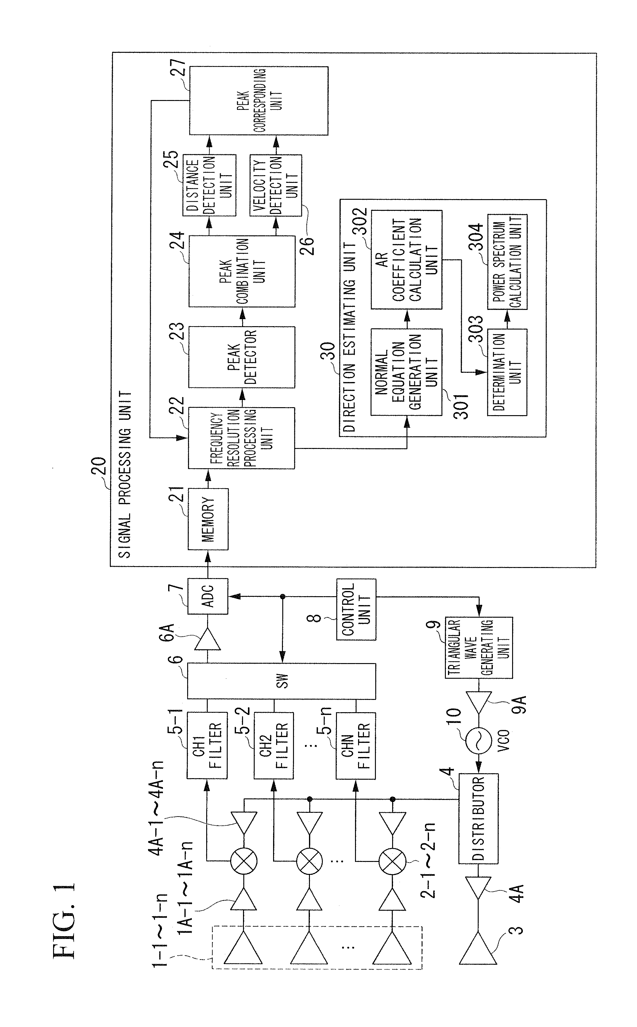
[0066]FIG. 1 is a block diagram of an electronic scanning radar apparatus in accordance with a first preferred embodiment of the present invention.

[0067]In the figure, the electronic scanning radar apparatus includes receiving antennas 1-1 through 1-n, mixers 2-1 through 2-n, a transmission antenna 3, a distributor 4, channel filters 5-1 through 5-n, a switching unit SW 6, an A / D convertor ADC 7, a control unit 8, a triangular wave generating unit 9, a voltage control oscillator VCO 10, and a signal processing unit 20. Further, there are amplifiers 1A-1 through 1A-n, which are individually provided between the receiving antennas 1-1 through 1-n and the mixers 2-1 through 2-n. Also there are amplifiers 4A-1 through 4A-n provided between the mixers 2-1 through 2-n and the distributor 4. Each of the amplifiers 4A-1 through 4A-n is correspondingly provided to each of the mixers 2-1 through 2-n. Further, an amplifier 4A is provided between the transmission antenna 3 and the distributor 4...

second embodiment

[0216]Next, descriptions will be given for an electronic scanning radar apparatus of the present embodiment with reference to figures.

[0217]FIG. 17 is a block diagram of the electronic scanning radar apparatus of the present embodiment.

[0218]A signal processing unit 20B of the present embodiment performs direction estimations based on a high resolution algorithm, similar to the case of the first embodiment.

[0219]In the following, identical symbols are used for identical configurations used in FIG. 1, and descriptions will be given for different parts from the case of the first embodiment.

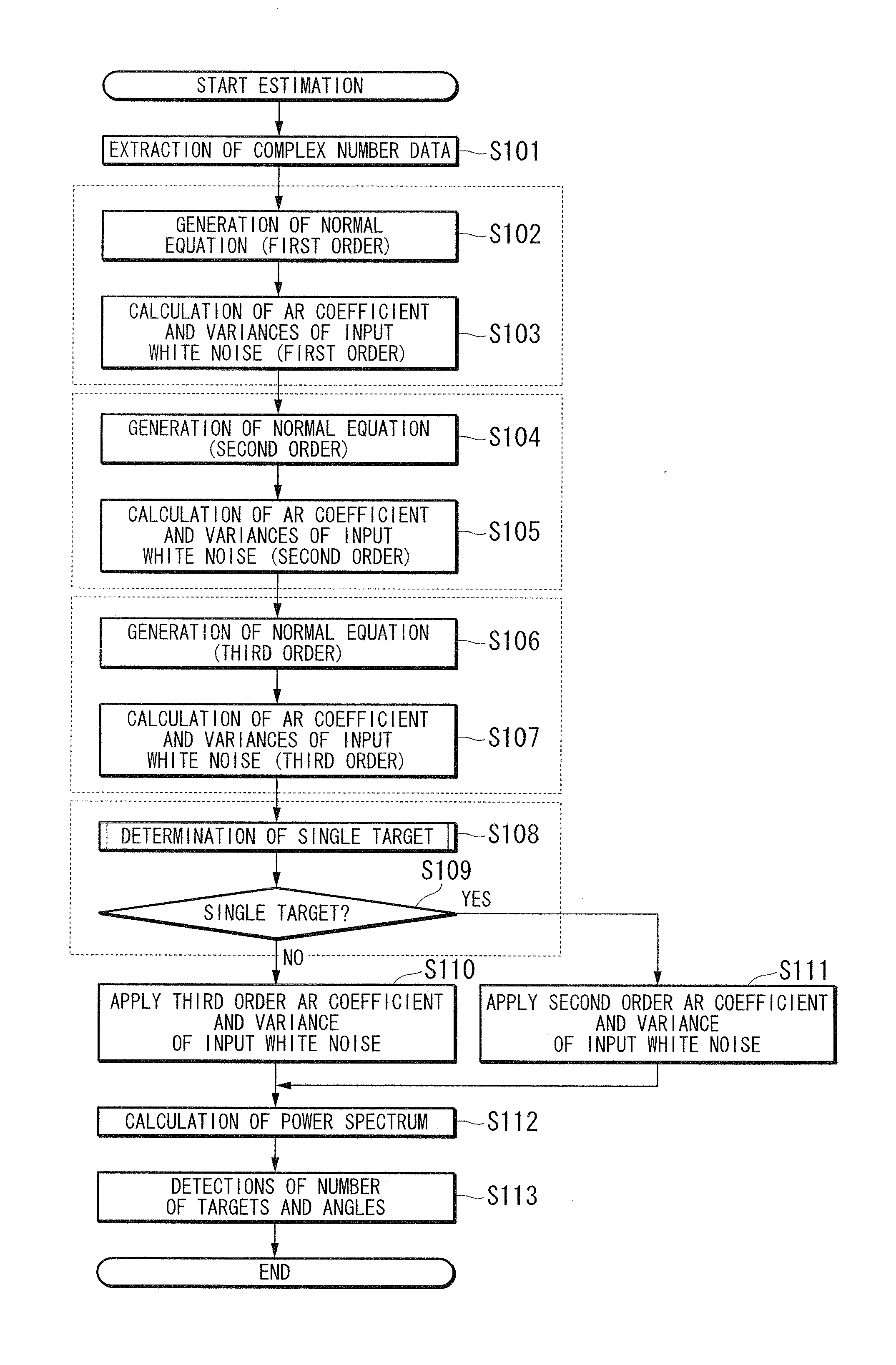
[0220]In the signal processing unit 20B, a frequency resolution processing unit 22B converts beat signals of an ascending region and a descending region for each antenna into complex number data. The frequency resolution processing unit 22B transmits frequency points and the complex number data to a peak detector 23B, in which the frequency points indicate the beat frequencies of the beat signals.

[0...

third embodiment

[0230]An electronic scanning radar apparatus in accordance with a third embodiment will now be explained with reference to figures.

[0231]FIG. 19 is a block diagram illustrating an example of the electronic scanning radar apparatus according to the present embodiment.

[0232]Unlike the case of the first embodiment, a signal processing unit 20C of the present embodiment uses a digital beam forming (DFB) process in advance for direction estimations, in which the resolution of DFB is lower than that of the AR spectrum estimation process or the like which includes a high resolution algorithm. After a first direction estimation is performed with the DBF, a second direction estimation is performed with the high resolution algorithm of the AR spectrum estimation process. For parts and configurations of FIG. 19 identical to those of FIG. 1 of the first embodiment, identical symbols are used and other parts different from FIG. 1 will be explained below.

[0233]As shown in the figure, a DBF proces...


PUM


Abstract

An electronic scanning radar apparatus includes a transmission unit configured to transmit a transmission wave, and a receiving unit including a plurality of antennas receiving a receiving wave coming from a target. The receiving wave is formed from a reflection wave of the transmission wave reflected at the target. A beat signal generation unit is configured to generate beat signals in response to the transmission wave and the receiving wave. A frequency resolution processing unit is configured to obtain complex number data calculated from beat frequencies having signal levels obtained by performing a frequency resolution for the beat signals based on a predetermined frequency width. A peak detector is configured to detect an existence of the target by detecting peak signal levels of the beat frequencies, and a direction detecting unit is configured to calculate an incoming direction of the receiving wave based on a normal equation having an order.

Description

BACKGROUND OF THE INVENTION[0001]1. Field of the Invention[0002]The present invention relates to an electronic scanning radar apparatus, a receiving wave direction estimating method, and a computer-readable storage media storing a receiving wave direction estimation program. More particularly, the present invention relates to an electronic scanning radar apparatus being preferable to be equipped in a moving body, a receiving wave direction estimating method, and a computer-readable storage media storing a receiving wave direction estimation program, in which the electronic scanning radar apparatus transmits a transmission wave to a target so as to detect the target by receiving a reflection wave of the transmission wave reflected from the target.[0003]Priority is claimed on Japanese Patent Application No. 2010-025950, filed Feb. 8, 2010, the content of which is incorporated herein by reference.[0004]2. Description of the Related Art[0005]All patents, patent applications, patent publ...

Claims


Application Information

Patent Timeline
IPC IPC(8): G01S13/04
CPCG01S3/74G01S13/345G01S13/931G01S13/584G01S13/42
Inventor KANAMOTO, JUNJI
Owner HONDA ELESYS CO LTD
Why Eureka
Try Eureka