Identification of a fault

a fault and identification technology, applied in the field of identification of faults, can solve the problems of providing a misleading or incomplete picture of signal performance, poor user experience, and often hidden intermittent issues, and achieve the effect of promoting accuracy in symbol recognition/detection and minimizing or eliminating demodulation errors

Active Publication Date: 2011-08-11
COMCAST CABLE COMM LLC
View PDF11 Cites 40 Cited by
  • Summary
  • Abstract
  • Description
  • Claims
  • Application Information

AI Technical Summary

Benefits of technology

In some embodiments, distortion compensation (pre-equalization) may be performed at a user terminal prior to transmission of a signal from the user terminal In some embodiments, distortion compensation (post-equalization) may be performed after the signal has been transmitted from the user terminal and received at a receiving device. The distortion compensation techniques may be used to correct for deficiencies or non-idealities in a network (e.g., the components or communication channel(s) thereof). For example, the distortion techniques may be used to minimize or eliminate demodulation errors at the receiving device, thereby promoting accuracy in terms of symbol recognition / detection.

Problems solved by technology

For example, standard metrics used to evaluate user terminal (e.g., modem) performance are subject to equalization and may provide a misleading or incomplete picture of signal performance.
Furthermore, intermittent issues are often hidden by equalization employed by user terminals.
Intermittent transmission problems often result in inconclusive troubleshooting and a poor user experience.
This often leads to a user repeatedly contacting the network operator to complain about issues such as failures and difficulties on the part of a technician in recreating an error condition.
When debugging a fault, traditional performance metrics are generalized and fail to provide an indication as to where the source of the fault is located.

Method used


Image

  • Identification of a fault
  • Identification of a fault
  • Identification of a fault

Examples


Embodiment Construction

It is noted that various connections between elements are discussed in the following description. It is noted that these connections are general and, unless specified otherwise, may be, for example, wired or wireless, direct or indirect, and that this specification is not intended to be limiting in this respect.

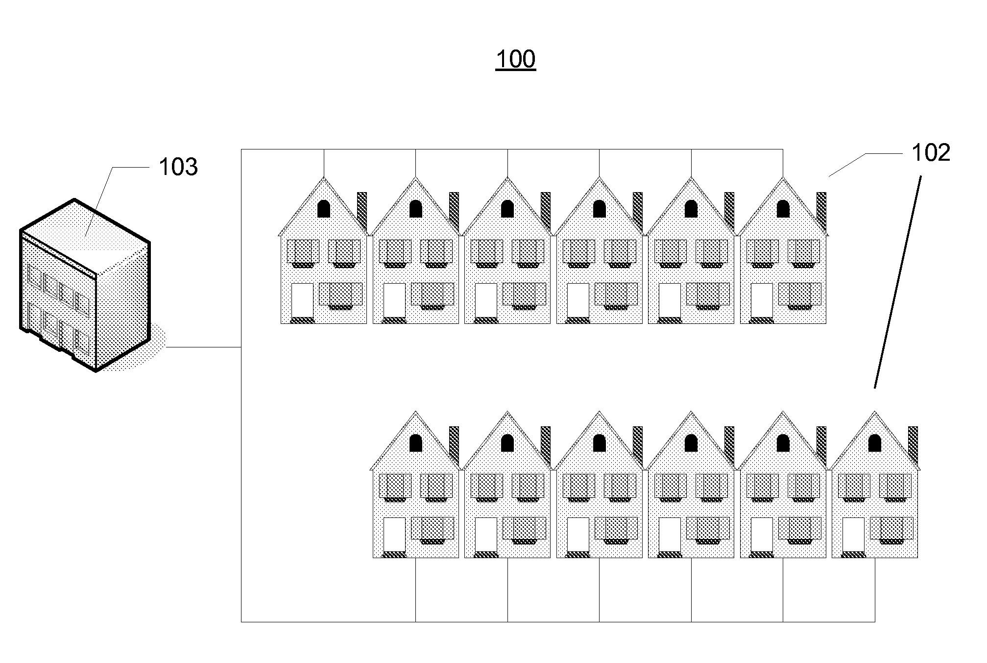
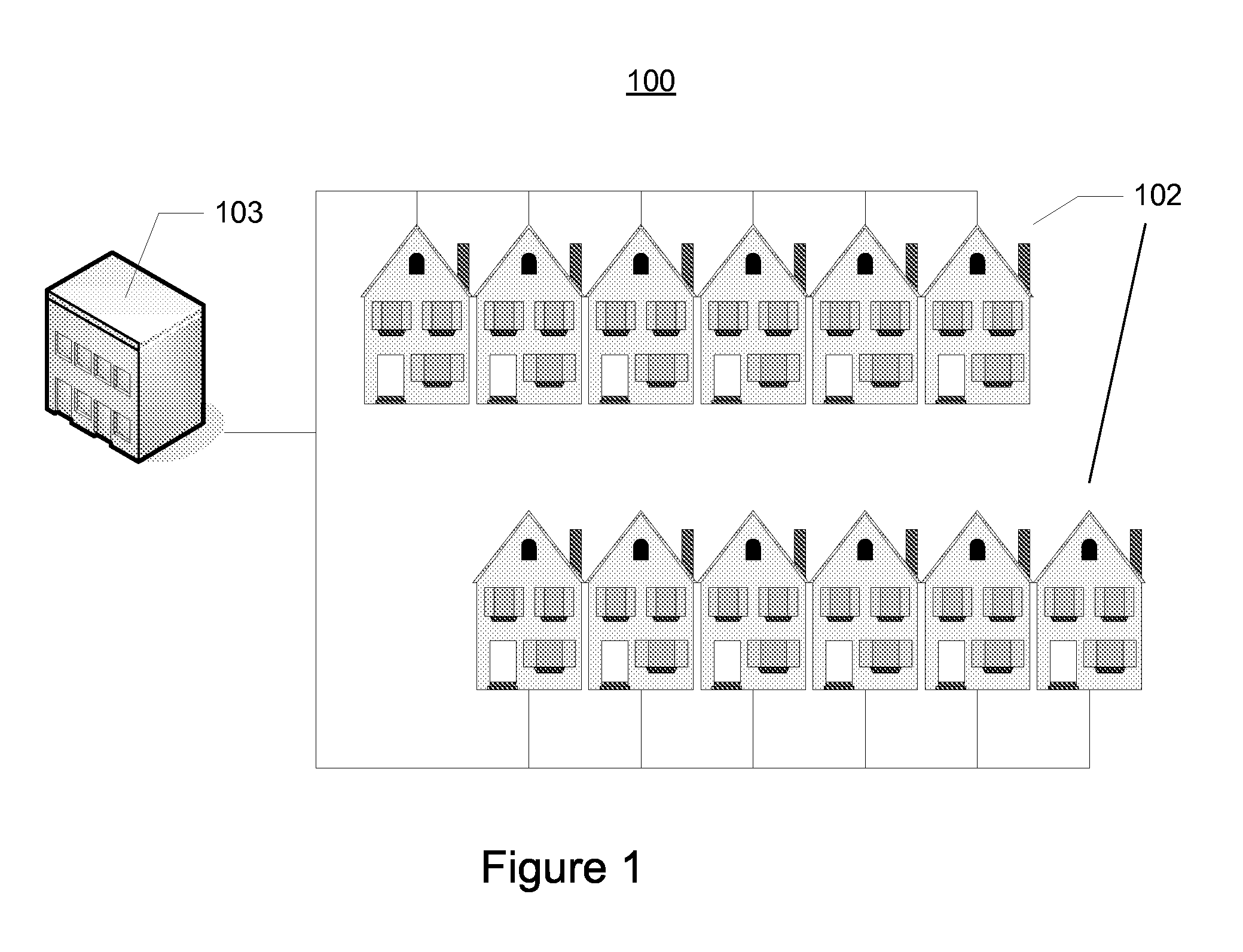
FIG. 1 illustrates an example information distribution network 100 on which many of the various features described herein may be implemented. Network 100 may be any type of information or content distribution network, such as satellite, optical fiber, coaxial cable, telephone, cellular, wireless, etc. The network may be a hybrid fiber / coax distribution network found in many television networks. Such networks 100 may use a series of interconnected lines 101 to connect multiple homes 102 to a provider's headend or central location 103. The central location 103 may transmit downstream information signals onto the lines 101, and each home 102 may have a tuner used to receive and ...


PUM


Abstract

An apparatus, method, and system are provided for determining a location of an error source. Equalization coefficients may be retrieved and an average period of time between localized peak amplitudes may be determined. The average period of time may be multiplied by a velocity of propagation associated with a communication channel to determine an approximate location of the error source. The equalization coefficients may correspond to the inverse of the frequency response associated with the communication channel and may be updated over time using replacement or combination (e.g., convolution) techniques.

Description

FIELD OF ARTThe features described herein generally relate to providing users with access to content over a network. More specifically, aspects of the disclosure describe identifying a likely or approximate location of a potential problem or error associated with a network.BACKGROUNDFrom the perspective of a service provider or network operator, the most common driver for user initiated contact related to service problems is typically caused by in-home wiring issues. For example, standard metrics used to evaluate user terminal (e.g., modem) performance are subject to equalization and may provide a misleading or incomplete picture of signal performance. Standard metrics generally provide a good representation of the user's overall experience, but the equalization can mask signal impairments which may manifest intermittently and not necessarily at the time of analysis.Furthermore, intermittent issues are often hidden by equalization employed by user terminals. Intermittent transmissio...

Claims


Application Information

Patent Timeline
Patent Type & Authority Applications(United States)
IPC IPC(8): H04L12/26
CPCH04L25/022H04L25/03019H04L2025/0342H04L67/18H04L43/0823H04L25/03H04L63/107H04L2025/03808H04L67/52
Inventor WOLCOTT, LAWRENCE D.CHANG, PHILLIP F.
Owner COMCAST CABLE COMM LLC
Why Eureka
Try Eureka