
Method and device for descaling a metal strip

a metal strip and descaling technology, applied in vacuum evaporation coating, manufacturing tools, coatings, etc., can solve the problems of large investment required for installation of this type of steel strip, inconvenient industrial descaling of wide steel strip, waste of resources, etc., to prevent oxidation processes, improve quality, and reduce waste of resources

Inactive Publication Date: 2011-08-11
SMS DEMAG AG
View PDF7 Cites 10 Cited by
  • Summary
  • Abstract
  • Description
  • Claims
  • Application Information

AI Technical Summary

Benefits of technology

The invention is a method and device for descaling a metal strip during production. The method involves plasma descaling the metal strip and then cooling it in a controlled way to prevent oxidation and maintain a good surface quality. The cooling unit uses a cooling roller with a coating made of a wear-resistant material that is a good thermal conductor. The method and device can improve the quality and efficiency of the metal strip production process.

Problems solved by technology

Therefore, installations of this type require very large investments.
In addition, the pickling process uses a tremendous amount of power and entails great expense for the elimination of wastewater and the regeneration of the hydrochloric acid, which is the type of acid usually used for normal steel.
However, with respect to their economy and the quality of the descaled surface, methods of these types are not suitable for the industrial descaling of wide steel strip.
The action of the plasma on the scale results in the removal of the oxides on the surface of the strip, and this is associated with an increase in the temperature of the strip, which can be a serious disadvantage.
An oxide film is unacceptable for further processing steps, such as cold rolling or the direct working of hot strip.
However, the concepts disclosed in this literature are aimed at cooling measures that are associated with considerable disadvantages in some cases or are relatively inefficient.
If the metal strip is treated with a cooling gas, the cooling rate is very low, and, in addition, a solution of this type is not possible in a vacuum.
The other proposed solutions offer almost no possibility of realizing a specific temperature program for the metal strip.
Systematic cooling of this type is not possible with the prior-art solutions.

Method used


Image

  • Method and device for descaling a metal strip
  • Method and device for descaling a metal strip
  • Method and device for descaling a metal strip

Examples


Embodiment Construction

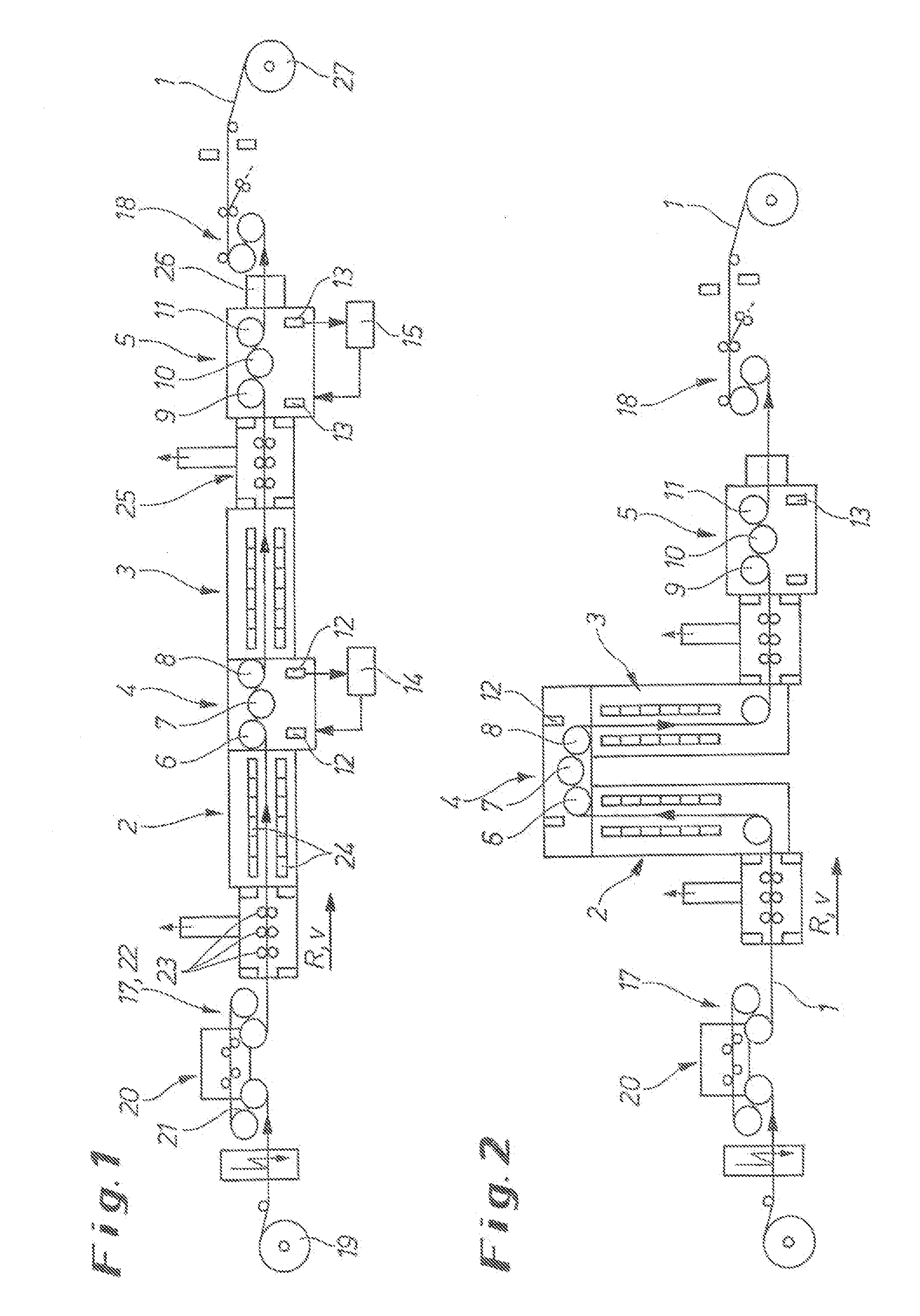
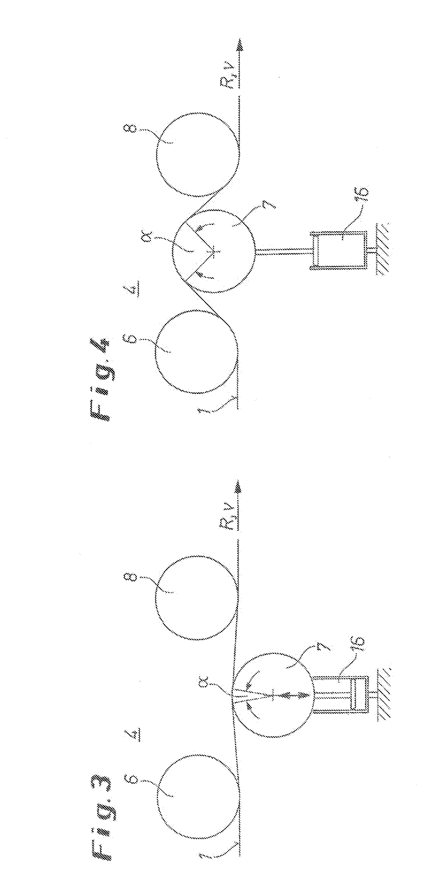
[0044]FIG. 1 shows a device for descaling a steel strip 1. This installation has a horizontal design. The steel strip 1 is unwound from a pay-off reel 19 and leveled in a stretcher-and-roller leveling machine 20 with the associated bridles 21 and 22, so that the metal strip 1 has the greatest possible flatness before the strip enters the process section of the plant under high tension.

[0045]The strip 1 passes through several vacuum locks 23 and into a first plasma descaling unit 2, in which the vacuum necessary for the plasma descaling is produced and maintained by vacuum pumps of known design. Electrodes 24 are installed in the plasma descaling unit 2 on both sides of the strip 1 and produce the plasma necessary for the descaling.

[0046]The plasma causes the surface of the strip to be heated on both sides, which can lead to heating of the entire cross section of the strip to a temperature of a maximum of 200° C. at the end of the plasma descaling unit 2. The degree of heating of the...


PUM

PropertyMeasurementUnit
temperatureaaaaaaaaaa

Abstract

A method and a device for descaling a metal strip, in which the metal strip is guided in a direction of conveyance through at least one plasma descaling unit in which it is subjected to a plasma descaling. The metal strip is subjected to an automatically controlled cooling process in a cooling unit following the plasma descaling in the one or more plasma descaling units in such a way that it has a well-defined temperature downstream of the cooling unit.

Description

CROSS-REFERENCE TO RELATED APPLICATIONS[0001]The present application is a Divisional application of U.S. patent application Ser. No. 11 / 886,397, filed Sep. 14, 2007, which is a 371 of International application PCT / EP2006 / 002429, filed Mar. 16, 2006, which claims priority of DE 10 2005 012 296.5, filed Mar. 17, 2005, the priority of these applications is hereby claimed and these applications are incorporated herein by reference.BACKGROUND OF THE INVENTION[0002]The invention concerns a method for descaling a metal strip, especially a hot-rolled strip of normal steel or a hot-rolled or cold-rolled strip of austenitic or ferritic stainless steel, in which the metal strip is guided in a direction of conveyance through at least one plasma descaling unit, in which it is subjected to a plasma descaling. The invention also concerns a device for descaling a metal strip.[0003]Steel strip must have a scale-free surface before it can be further processed, e.g., by cold rolling, by the applicatio...

Claims


Application Information

Patent Timeline
Patent Type & Authority Applications(United States)
IPC IPC(8): C23C14/02
CPCB08B7/0035B21B15/005B21B45/04B21B45/06B21B45/0203C23C2/02C23C2/004C23C2/024C23C2/0224C23C2/0035C23C2/0038C23C2/52
Inventor BEHRENS, HOLGERBRISBERGER, ROLFFROMMANN, KLAUSKRETSCHMER, MATTHIASZERBE, RUDIGERSENOKOSOV, EVGENY STEPANOVICHSENOKOSOV, ANDREI EVGENIEVICH
Owner SMS DEMAG AG
Learn More