Checking Functionality of Fuel Tank Vapor Pressure Sensor

a technology of vapor pressure sensor and fuel tank, which is applied in the direction of condensed fuel collection/return, charge feed system, non-fuel substance addition to fuel, etc., can solve the problems of unique challenges in the architecture of a non-integrated fuel system, and achieve the effect of reducing cost and lowering overall emissions

Inactive Publication Date: 2011-08-18
GM GLOBAL TECH OPERATIONS LLC
View PDF6 Cites 23 Cited by
  • Summary
  • Abstract
  • Description
  • Claims
  • Application Information

AI Technical Summary

Benefits of technology

[0008]Under normal running conditions, the air reference port hose does not affect the output of fuel tank vapor pressure sensor because the air reference port is open to atmosphere. The system provides a reliable check on the operation of the fuel tank pressure sensor without opening the Diurnal Control Valve (DCV) and without need for a second fuel tank vapor pressure sensor.
[0009]The system lowers overall emissions and reduces cost associated with the eliminated second fuel tank vapor pressure sensor, manifold, and a hose connecting the manifold to the carbon canister. The system avoids failure modes that would prevent the second sensor from operating correctly while working concurrently with correct operation of the first sensor.

Problems solved by technology

The architecture of a non-integrated fuel system presents unique challenges to verify leak integrity without redundant pressure sensors or excessive emissions.

Method used


Image

  • Checking Functionality of Fuel Tank Vapor Pressure Sensor
  • Checking Functionality of Fuel Tank Vapor Pressure Sensor

Examples


Embodiment Construction

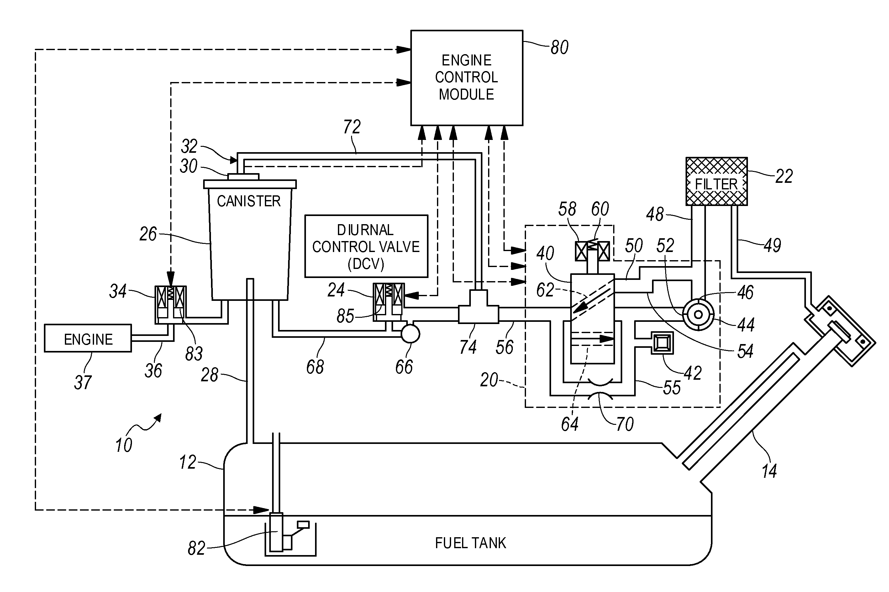
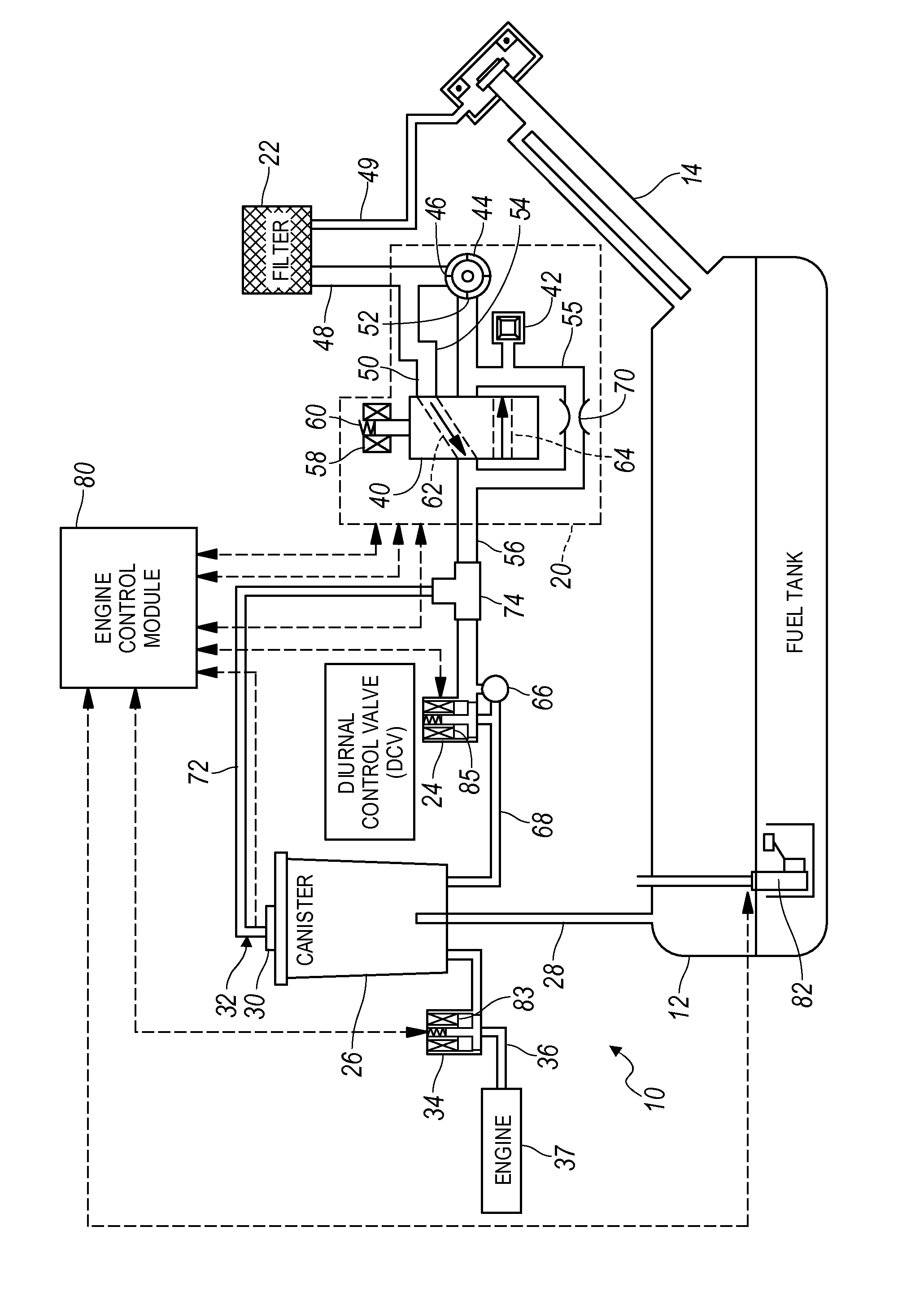
[0011]The fuel tank emission system 10 shown in the drawing, includes a fuel tank 12; a file pipe 14 through which fuel enters the tank 12; an evaporative leak check module (ELCM) 20; filter 22; a normally-closed diurnal control valve (DCV) 24; carbon canister 26, connected by a passage 28 to tank 12; fuel tank vapor pressure sensor (FTVPS) 30; an atmosphere reference port 32; and a purge valve 34, connected by a passage 36 to an engine 37. The FTVPS 30 is used to check the fuel system vapor space for the presence of a leak equivalent to about a 0.020 inch (0.508 millimeters) diameter hole.

[0012]Fuel vapor generated in tank 12 is at least partially vented through a first vapor flow path, which includes passage 28 and canister 26. Activated carbon, similar to charcoal, contained in canister 26 collects and stores the hydrocarbons. When the engine is running, air is drawn through canister 26, and the hydrocarbons are drawn into the engine 37.

[0013]The tank vapor pressure sensor 30 is ...


PUM


Abstract

A vehicle fuel emissions system includes a fuel tank, a tank pressure sensor indicating a pressure differential between the tank and a port communicating with the atmosphere, a pump for selectively producing vacuum in the tank, and a passage connecting the pump and a pressure sensor air reference port external to the system.

Description

BACKGROUND OF INVENTION[0001]The present invention relates generally to an apparatus for checking the functionality of a fuel tank vapor pressure sensor using vacuum produced by a pump at an atmospheric port.[0002]A non-integrated vehicle fuel system includes a normally-sealed fuel tank. Fuel system integrity is verified by the presence of pressure or vacuum created by temperature difference or a leak check pump. If the system holds pressure or vacuum above a certain threshold, the fuel system is considered leak free.[0003]Because the fuel system integrity determination relies upon the tank vapor pressure sensor reading, a rationality check must be performed on the fuel tank vapor pressure sensor. Primary failure modes such as sensor-offset or sensor-stuck-in-range must be checked.[0004]The architecture of a non-integrated fuel system presents unique challenges to verify leak integrity without redundant pressure sensors or excessive emissions. For example, in order to reliably ensur...

Claims


Application Information

Patent Timeline
Patent Type & Authority Applications(United States)
IPC IPC(8): F02M33/02
CPCF02M25/0809
Inventor DER MANUELIAN, RAFFIKALVELAGE, KENNETH J.MCCARTHY, TIMOTHY E.
Owner GM GLOBAL TECH OPERATIONS LLC
Why Eureka
Try Eureka