Barnacle Fouling Tool

Inactive Publication Date: 2011-08-18
TILLEY GLENN
View PDF6 Cites 42 Cited by
  • Summary
  • Abstract
  • Description
  • Claims
  • Application Information

AI Technical Summary

Benefits of technology

[0013]It is therefore an object of the present invention to provide an antifouling device that can prevent barnacle and fouling development along the outer surface of a seismic surveying streamer cable that provides continuous motion along the length of the streamer, including fore and aft motion. One installation per streamer per deployment can be utilized to prevent fouling buildup.
[0014]Another object of the present invention is to provide an antifouling device that provides a switching mechanism

Problems solved by technology

The buildup of marine growth, such as barnacles and other organisms, can cause streamer fidelity loss and increased drag on the cable.
These methods are both expensive and time consuming.
They stop production data acquisition and result in surveying down time, adding significant opportunity cost to the seismic contractor.
Labor costs for cleaning the streamers are also higher, along with associated risks with these manual operations.
These include the opportunity for crew injury as the streamer is recovered from the water and manually cleaned, as well as the potential for damaging the streamer while being ha

Method used


Image

  • Barnacle Fouling Tool
  • Barnacle Fouling Tool
  • Barnacle Fouling Tool

Examples


Embodiment Construction

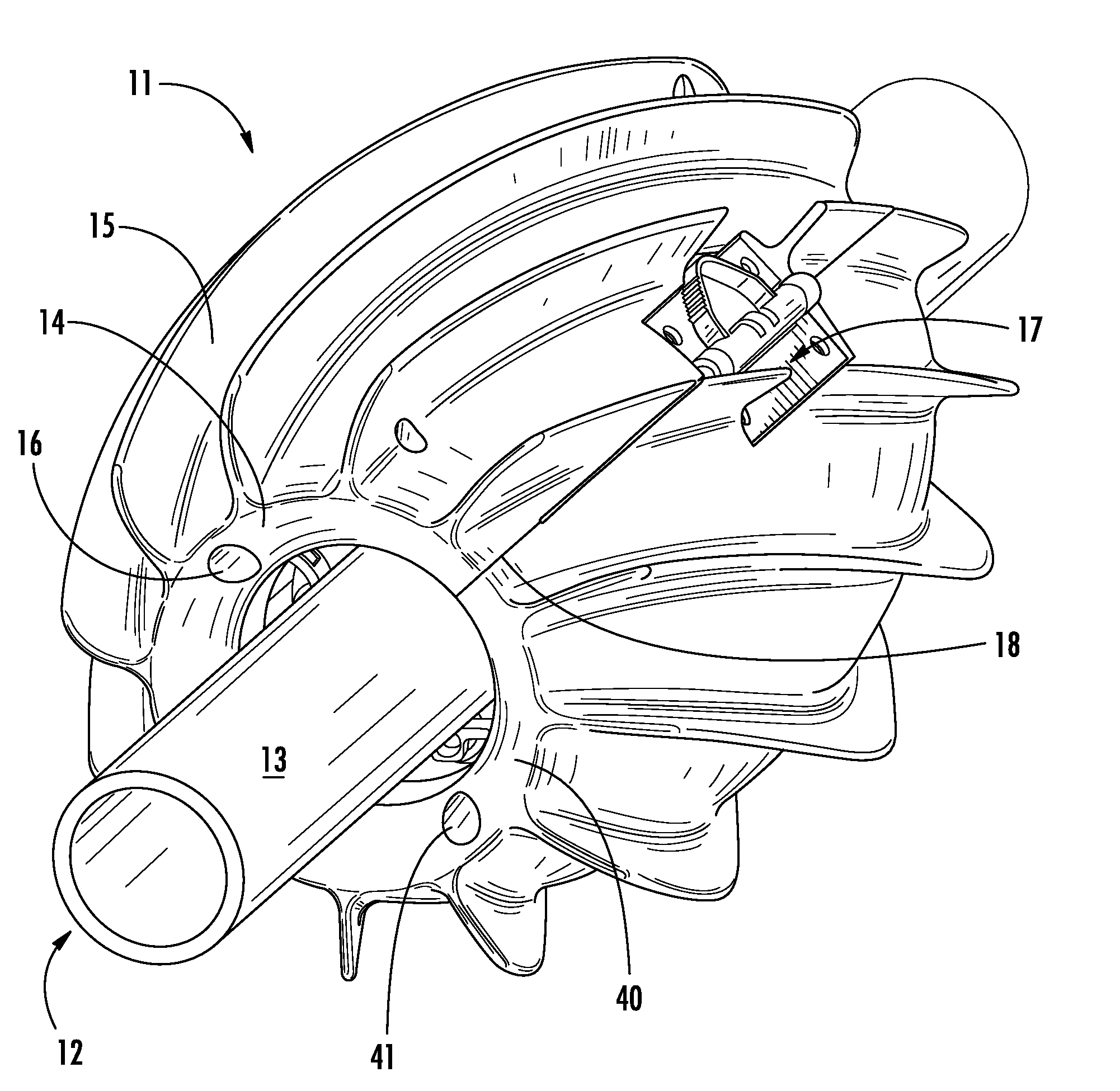
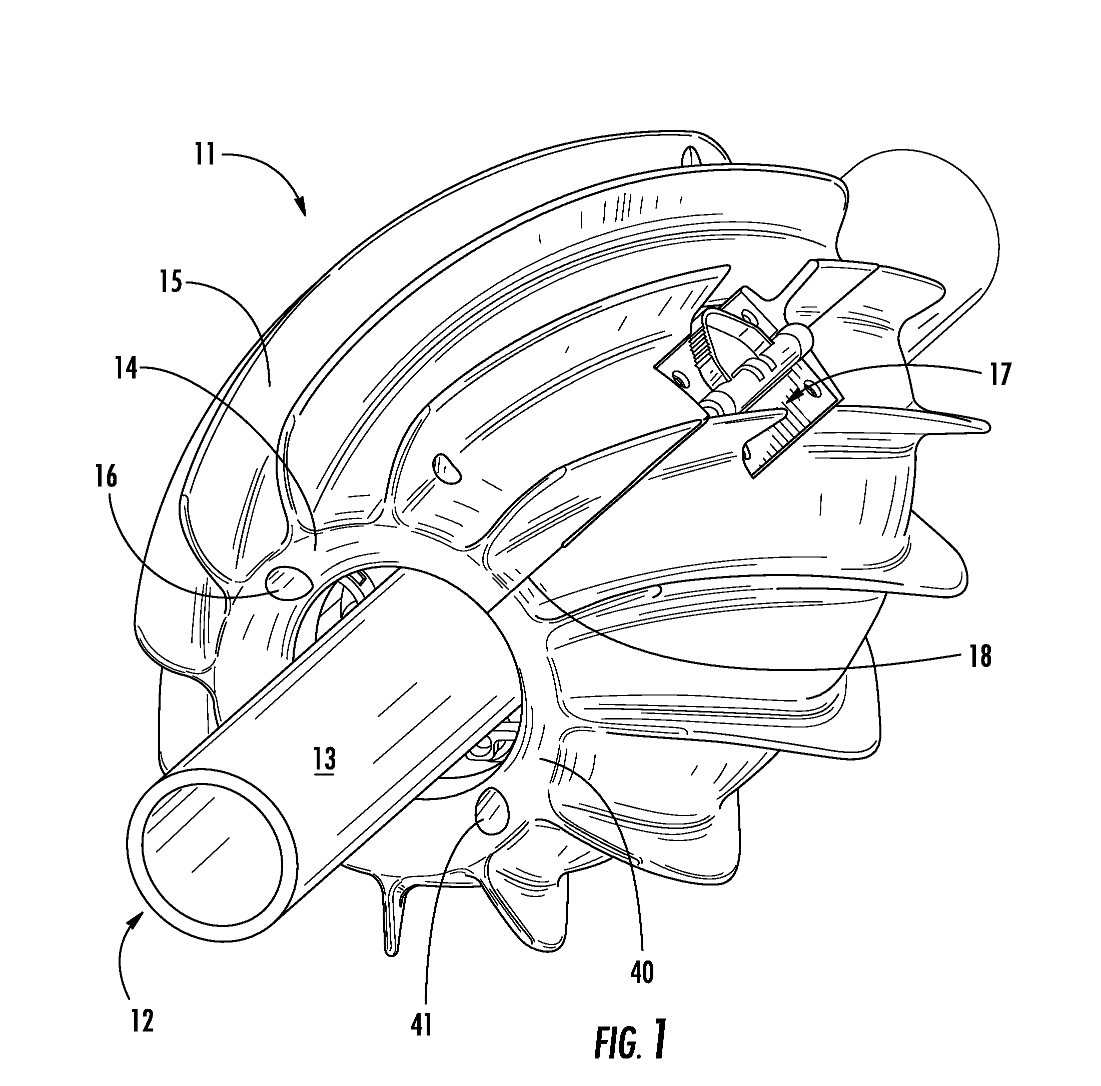
[0025]Referring now to FIG. 1, there is shown an isometric view of the cylindrical antifouling device 11 clamped around the periphery of a seismic streamer cable 12. The antifouling device 11 is comprised of two opposing shells 14, 40 joined together with a hinge along one edge and a securing clamp 17 along a second edge 18. The clamp 17 is used to join the two shells 14, 40 around the outer surface 13 of the streamer cable, as well as act as a release point for the two shells 14, 40. The device 11 translates along and rotates around the streamer cable 12, contacting the streamer outer surface 13 along a surface area patch defined by the contact area between the inner wheels and the streamer outer surface 13. Longitudinal holes 14, 41 allow penetration of a connecting rod between a first and second stop ring, which act to switch the direction of the interior wheels and change the translation and rotation directions of the device 11. For clarity, the stop rings and connecting rods ar...


PUM

PropertyMeasurementUnit
Lengthaaaaaaaaaa
Adhesion strengthaaaaaaaaaa

Abstract

Disclosed is a flow-driven antifouling device for a seismic marine streamer cable. A cylindrical housing is circumferentially mounted to a submerged, circular cable. Fluid flow over the cable provides motive power to rotate the device around the outer surface of the cable, preventing barnacles, marine growth and other fouling accumulation. Interior wheels contact the cable outer surface to disrupt fouling growth and control the direction of travel along the length of the cable. Radially-protruding vanes utilize the local fluid flow over the cable to apply a rotation to the device, powering its movement. The orientation of the inner wheels determines corkscrew direction, allowing forward and aft travel along the cable. Continuous and uninterrupted motion prevents fouling development, which improves the fidelity of seismic sensors and decreases drag on the cable.

Description

CROSS REFERENCE TO RELATED APPLICATION[0001]This application claims the benefit of U.S. Provisional Application No. 61 / 305,260 filed on Feb. 17, 2010, entitled “Barnacle Fouling Tool”BACKGROUND OF THE INVENTION[0002]1. Field of the Invention[0003]The present invention relates to marine surveying equipment and towed seismic sensors known as streamers. More specifically, this invention relates to devices utilized to continuously traverse submerged streamers for the purposes of preventing adhesion of marine growth that can disrupt signal transfer fidelity of imbedded sensors and increase cable drag.[0004]2. Description of the Prior Art[0005]Marine seismic surveying utilizes a method of reflection seismology to create a model of the seabed surface and the physical properties underlying the seafloor. Typically, seismic sensor lines called streamers are towed behind a maritime vessel near the ocean surface. An external energy source produces an energy wave directed at the seafloor, which ...

Claims


Application Information

Patent Timeline
IPC IPC(8): B08B1/04
CPCB08B17/02G01V13/00G01V1/201B63C11/52B63B59/10
Inventor TILLEY, GLENN
Owner TILLEY GLENN
Why Eureka
Try Eureka