Engine starter with improved fixing structure of auxiliary electromagnetic switch

Active Publication Date: 2011-08-18
DENSO CORP
View PDF10 Cites 7 Cited by
  • Summary
  • Abstract
  • Description
  • Claims
  • Application Information

AI Technical Summary

Benefits of technology

[0017]Consequently, without fixing the fixture along with the auxiliary electromagnetic switch to both the starter main body and the main electromagnetic switch, flex

Problems solved by technology

Consequently, the terminal voltage of the battery drops rapidly and thereby may cause an instantaneous power failure to occur.
Consequently, wear of the pinion and the ring gear will increase, thereby lowering durability of the starter and the engine.
In addition, a high level of noise will be generated during the establishment of engagement between the pinion and the ring gear.
Moreover, with

Method used


Image

  • Engine starter with improved fixing structure of auxiliary electromagnetic switch
  • Engine starter with improved fixing structure of auxiliary electromagnetic switch
  • Engine starter with improved fixing structure of auxiliary electromagnetic switch

Examples


Example

First Embodiment

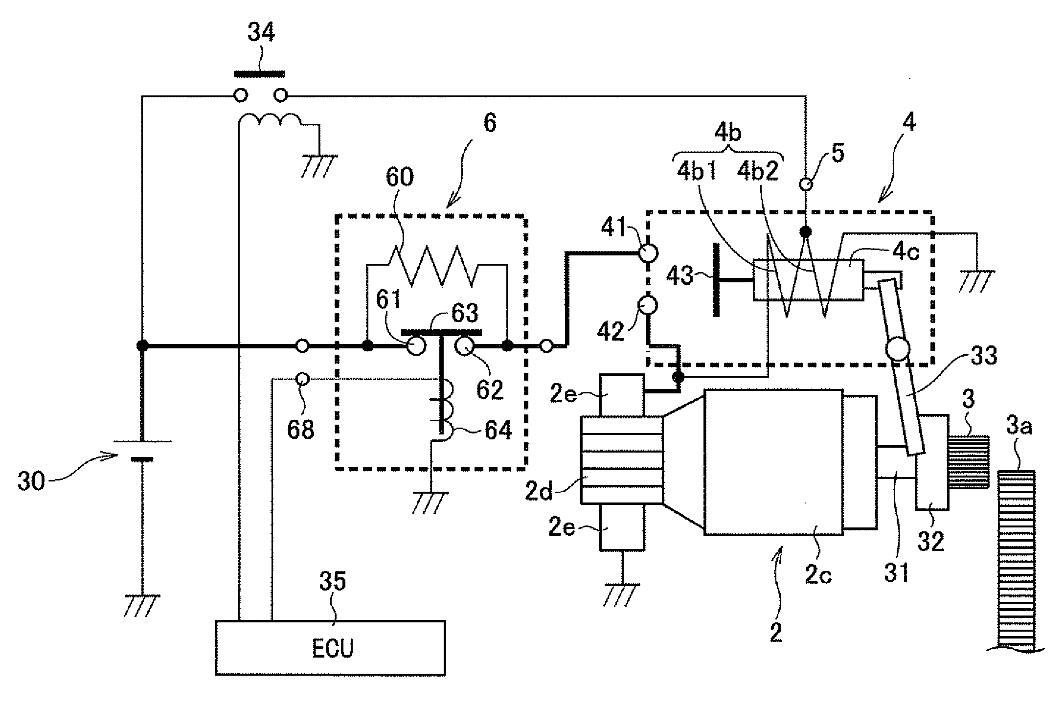
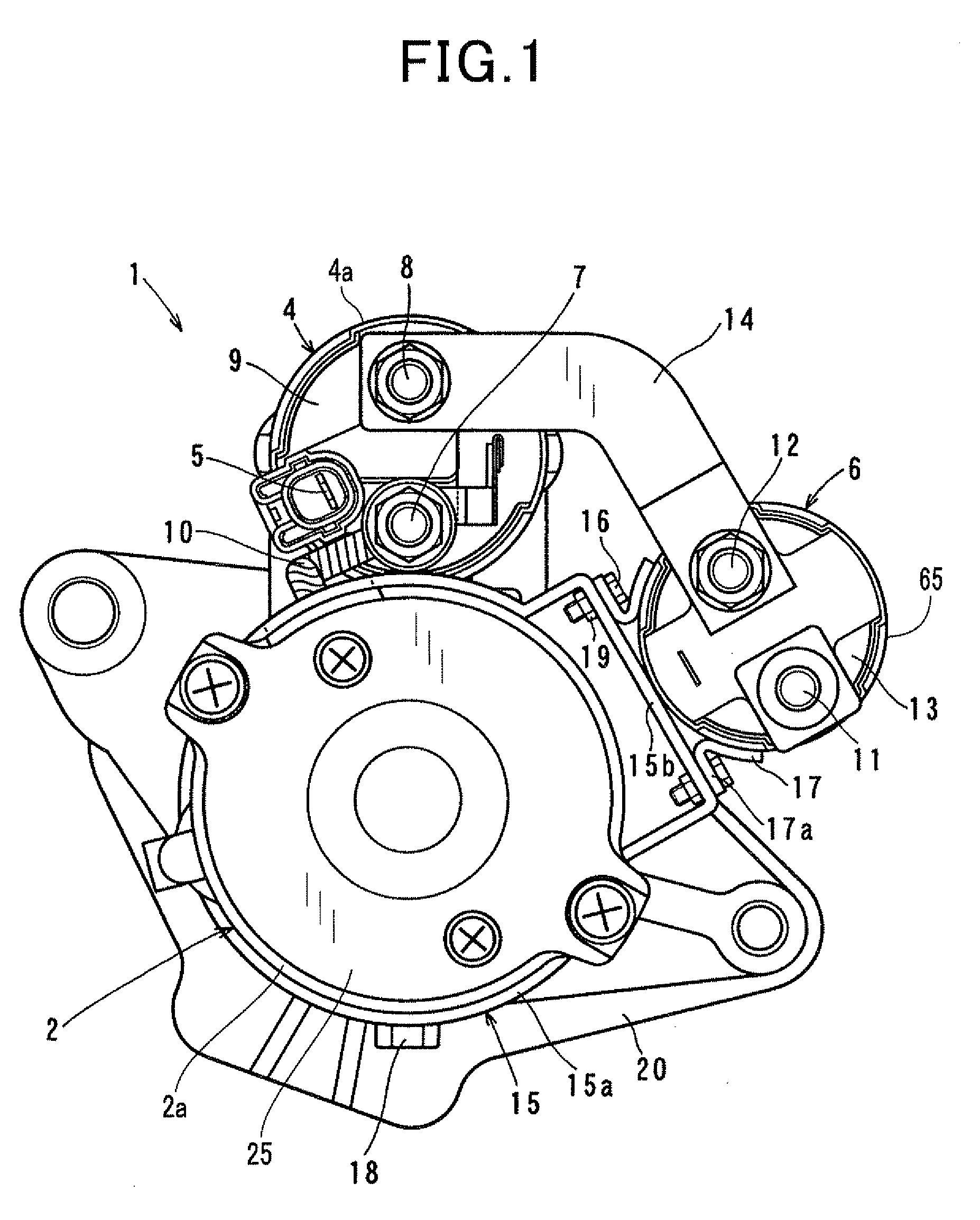
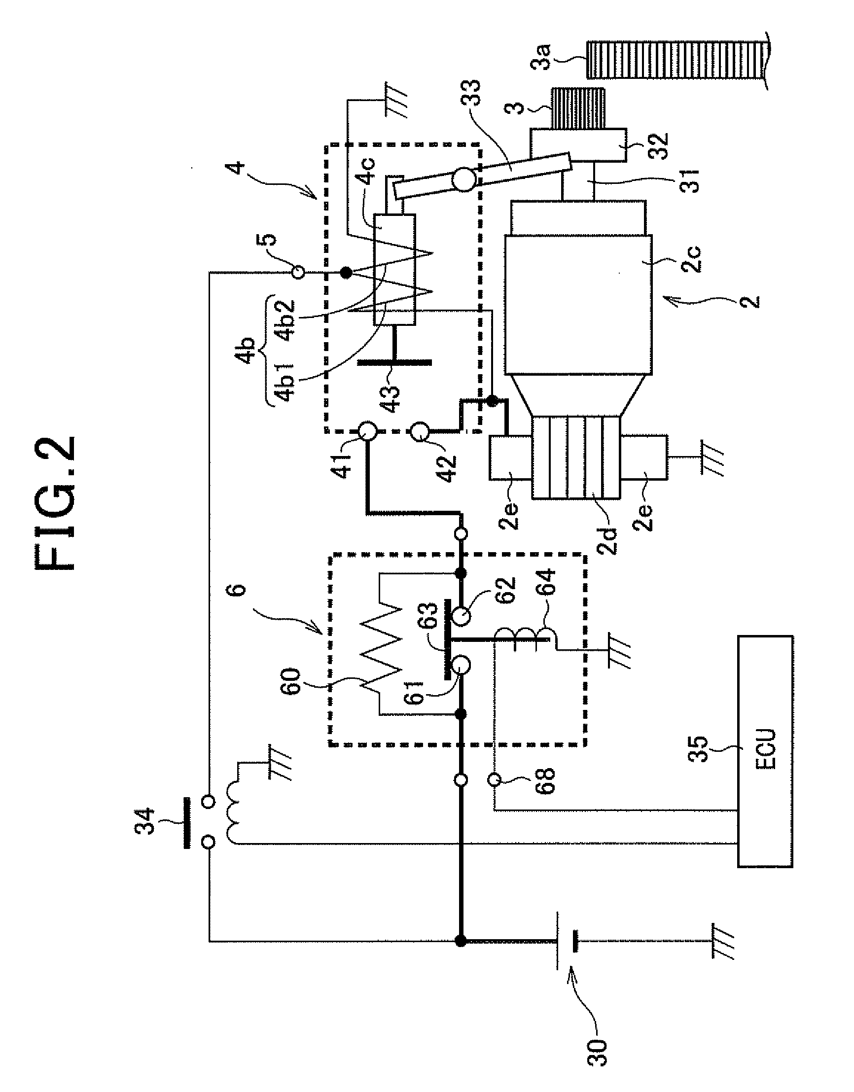
[0036]FIGS. 1 and 2 together show the overall configuration of a starter 1 according to the first embodiment of the invention. The starter 1 is designed to start an internal combustion engine of a motor vehicle.

[0037]As shown in FIGS. 1 and 2, the starter 1 includes: a motor 2 that generates torque upon being supplied with electric power; a pinion 3 that is configured to mesh with a ring gear 3a of the engine to transmit the torque generated by the motor 2 to the engine; a shift lever 33 that is configured to shift the pinion 3 in the axial direction of the starter 1 to bring the pinion 3 into and out of mesh with the ring gear 3a; a main electromagnetic switch 4 that selectively opens and closes an electric circuit for supplying electric power from a battery 30 to the motor 2 (to be simply referred to as motor circuit hereinafter); an auxiliary electromagnetic switch 6 that switches the motor circuit between a high-resistance path and a low-resistance path; and a re...

Example

Second Embodiment

[0096]FIG. 6 shows the configuration of a fixing band 15 according to the second embodiment of the invention.

[0097]As shown in FIG. 6, in the present embodiment, the fixing band 15 is also configured to include a band portion 15a and a seat portion 15b.

[0098]The seat portion 15b is identical to the seat portion 15b according to the first embodiment. However, the band portion 15a is different from the band portion 15a according to the first embodiment.

[0099]More specifically, in the present embodiment, the band portion 15b is divided in its circumferential direction to have an opposite pair of end parts 15f. The end parts 15f are bent to extend radially outward and face each other in the circumferential direction with a gap formed therebetween. In addition, each of the end parts 15f has a through-hole 15f1 formed therein.

[0100]In fixing the fixing band 15 to the motor yoke 2a, the fixing band 15 is first placed so that the band portion 15a of the fixing band 15 surr...

Example

Third Embodiment

[0106]FIG. 7 shows the configuration of a fixing band 15 according to the third embodiment of the invention.

[0107]As shown in FIG. 7, in the present embodiment, the fixing band 15 is also configured to include a band portion 15a and a seat portion 15b.

[0108]The band portion 15a is identical to the band portion 15a according to the first embodiment; thus it can be fixed to either the motor yoke 2a or the yoke 4a of the main electromagnetic switch 4 in the same manner as described in the first embodiment.

[0109]However, the seat portion 15b is different from the seat portion 15b according to the first embodiment. Specifically, referring further to FIG. 8C, in the present embodiment, the seat portion 15b has a pair of slits 15g that are formed through the end wall 15d1 to extend parallel to each other with a predetermined distance therebetween.

[0110]On the other hand, the auxiliary electromagnetic switch 6 includes, as shown in FIGS. 8A-8B, a pair of brackets 17 each of...


PUM


Abstract

Disclosed is a starter for starting an engine. The starter includes a starter main body, a main electromagnetic switch, and an auxiliary electromagnetic switch. The starter main body includes a motor that generates torque upon being supplied with electric power. The main electromagnetic switch is provided for selectively opening and closing an electric circuit for supplying electric power from a battery to the motor. The auxiliary electromagnetic switch is provided for selectively switching the electric circuit between a high-resistance path and a low-resistance path. The starter is characterized in that the auxiliary electromagnetic switch is fixed to a fixture, and the fixture is fixed to only one of the starter main body and the main electromagnetic switch.

Description

CROSS-REFERENCE TO RELATED APPLICATION[0001]This application is based on and claims priority from Japanese Patent Application No. 2010-33919, filed on Feb. 18, 2010, the content of which is hereby incorporated by reference in its entirety into this application.BACKGROUND OF THE INVENTION[0002]1. Technical Field of the Invention[0003]The present invention relates to engine starters which include a motor that generates torque for starting an engine, a main electromagnetic switch for selectively opening and closing an electric circuit for supplying electric power from a battery to the motor, and an auxiliary electromagnetic switch for selectively switching the electric circuit between a high-resistance path and a low-resistance path.[0004]2. Description of the Related Art[0005]Conventionally, a starter for starting an internal combustion engine generally includes a motor that generates torque for starting the engine and an electromagnetic switch that selectively opens and closes an ele...

Claims


Application Information

Patent Timeline
IPC IPC(8): F02N11/08H02K11/00
CPCF02N11/087F02N2250/02F02N15/006
Inventor YAMADA, KAZUO
Owner DENSO CORP
Why Eureka
Try Eureka