Battery protection circuit and method for energy harvester circuit

a protection circuit and energy harvester technology, applied in the field of energy harvesters, can solve the problems of small amount of energy available from a harvester, unpredictable, permanent damage, etc., and achieve the effect of/or other components, and preventing surge current damage to inductors

Active Publication Date: 2011-08-18
INTEL CORP
View PDF19 Cites 26 Cited by
  • Summary
  • Abstract
  • Description
  • Claims
  • Application Information

AI Technical Summary

Benefits of technology

[0010]It is another object of the invention to provide a circuit and method for preventing surge current damage to inductors and / or other components in DC-DC converter circuits coupled to an energy harvester.
[0011]It is another object of the invention to provide a circuit and method for both protecting batteries or supercapacitors in which harvested energy is stored and preventing surge current damage to inductors and / or other components in DC-DC converter circuits coupled to an energy harvester.

Problems solved by technology

The amount of energy available from a harvester usually is small and unpredictable, so intermediate energy storage is often required in these applications to provide for system power needs when energy from the harvester is unavailable or insufficient.
If battery 6 is fully charged to VBAT(max), then further charging may permanently damage it.

Method used


Image

  • Battery protection circuit and method for energy harvester circuit
  • Battery protection circuit and method for energy harvester circuit
  • Battery protection circuit and method for energy harvester circuit

Examples


Embodiment Construction

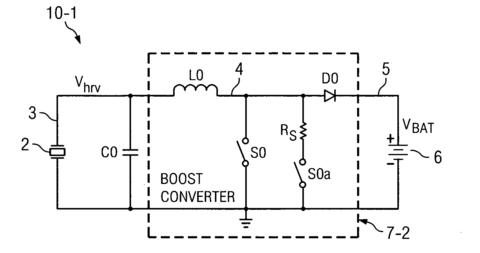
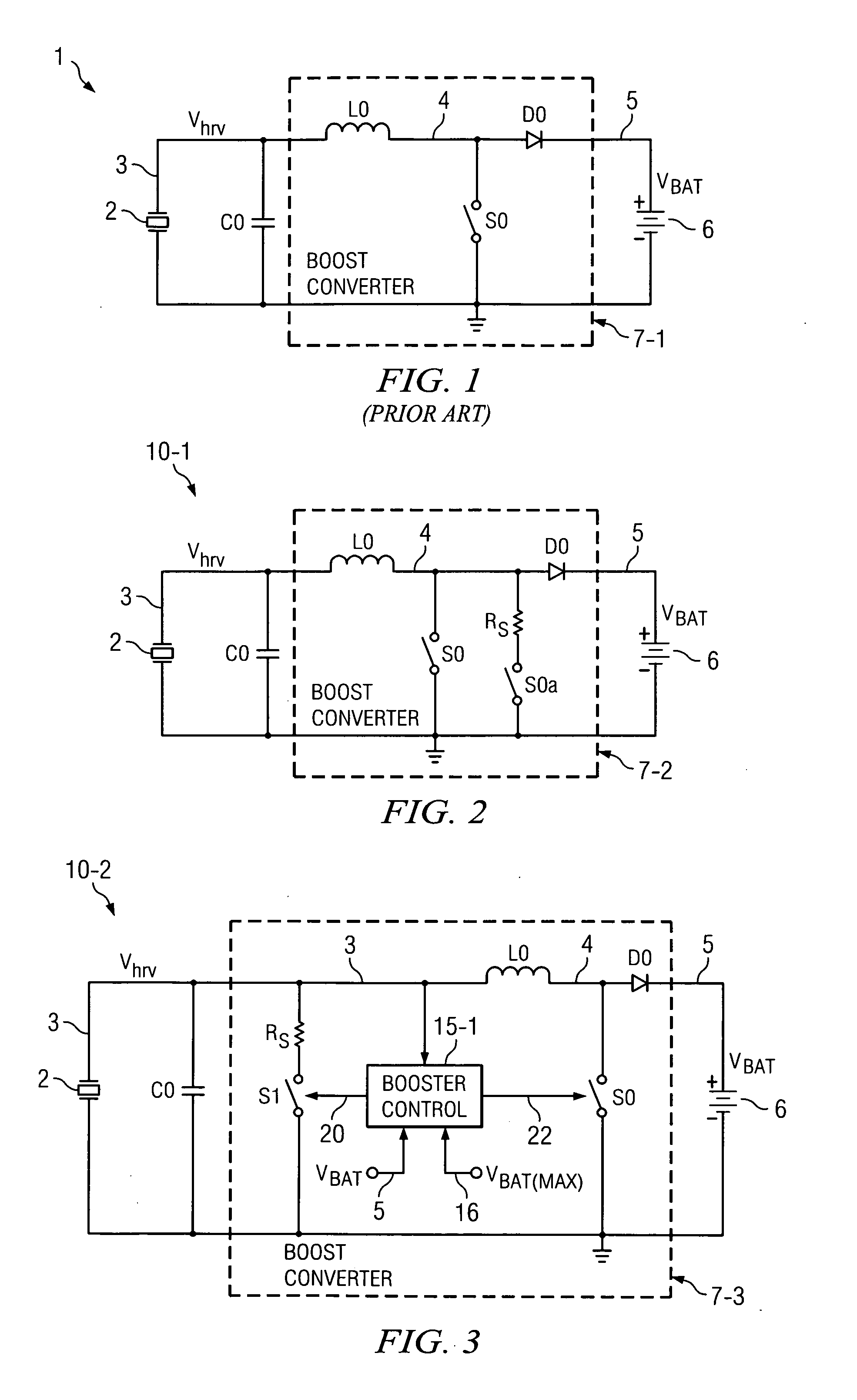
[0029]FIG. 2 shows a circuit 10-1 including energy harvester 2 which produces a harvested voltage Vhrv on a conductor 3. (Vhrv either is a DC voltage generated by a suitable rectifier that rectifies AC energy generated by a harvester such as an inductive or piezo electric harvester, or is a DC voltage directly generated by a harvester such as a thermopile harvester or a solar cell harvester.) Conductor 3 is connected to one terminal of filter capacitor C0 and also to the input of a conventional boost converter 7-2. The other terminal of capacitor C0 is connected to ground. Boost converter 7-2 can be considered to be a power management circuit that controls the flow of harvested energy from conductor 4 to battery / supercapacitor 6 and / or a load.

[0030]Boost converter 7-2 includes inductor L0 coupled between conductor 3 and conductor 4. As in Prior Art FIG. 1, conductor 4 in FIG. 2 is connected to one terminal of switch S0 and to the anode of diode D0. The other terminal of switch S0 is...


PUM


Abstract

Power management circuitry (7-2,3,4) for converting a harvested voltage (Vhrv) to an output voltage (VBAT) applied to a battery (6) includes an inductor (L0) having a first terminal (3) coupled to receive the harvested voltage (Vhrv) and a second terminal coupled to a first terminal of a first switch (S0). The power management circuitry transfers the current generated by an energy harvester (2) to the battery if it (6) is not fully charged, and shunts the current away from the battery (6) to avoid overcharging if it is fully charged.

Description

BACKGROUND OF THE INVENTION[0001]The present invention relates generally to energy harvesters, such as vibration energy harvesters, for scavenging or harvesting very low levels of energy, and more particularly to circuits and methods for protecting batteries or supercapacitors in which the harvested energy is stored. The invention also relates to circuits and methods for preventing surge current damage to inductors and / or other circuit components in DC-DC converter circuits or other power management circuitry that receives energy from the outputs of energy harvesters.[0002]Various very low power, i.e., “nano-power”, integrated circuits that require extremely low amounts of operating current have been developed which can be powered by very small amounts of power scavenged or harvested from ambient solar, vibrational, thermal, and / or biological energy sources by means of micro-energy harvesting devices and then stored in batteries or supercapacitors. (The term “nano-power” as used her...

Claims


Application Information

Patent Timeline
Patent Type & Authority Applications(United States)
IPC IPC(8): H02J7/04
CPCH02J7/0029H02M3/155H02J2007/0059H02J7/0052H02J2207/20H02J7/00302H02J7/00
Inventor IVANOV, VADIM V.SCOONES, KEVIN A.
Owner INTEL CORP
Why Eureka
Try Eureka