Image processing apparatus and image processing method

a technology of image processing apparatus and image processing method, which is applied in the direction of color signal processing circuit, picture signal generator, solid-state device signal generator, etc., can solve the problems of blurred image, low resolution of especially a peripheral region of capturing image, and use of low-performance lenses, so as to suppress the generation of artifacts

Active Publication Date: 2011-08-18
CANON KK
View PDF3 Cites 21 Cited by
  • Summary
  • Abstract
  • Description
  • Claims
  • Application Information

AI Technical Summary

Benefits of technology

[0029]According to these aspects, a blur of an image caused by an imaging optical system can be corrected while suppressing generation of artifacts.

Problems solved by technology

Conversely, when an inexpensive low-performance lens is used, the resolution of especially a peripheral region of a capturing image drops considerably.
Each star in an image captured using a low-performance lens, however, is not a point image but is blurred.
However, if a low-performance lens is used, an image in which hair is blurred is obtained.
However, when an imaging optical system which suffers a large blur is used in the same environment, light does not form a point on the light-receiving surface, and has a certain spread.
In this way, a blur cannot be perfectly removed due to deviation from ideal conditions, that is, the presence of noise included in the capturing image, that of the frequency at which the OTF=0, and so forth.

Method used


Image

  • Image processing apparatus and image processing method
  • Image processing apparatus and image processing method
  • Image processing apparatus and image processing method

Examples


first embodiment

[0043]The first embodiment will explain an image capturing apparatus which corrects a blur of an image caused by an imaging optical system while suppressing generation of false colors.

[Apparatus Arrangement]

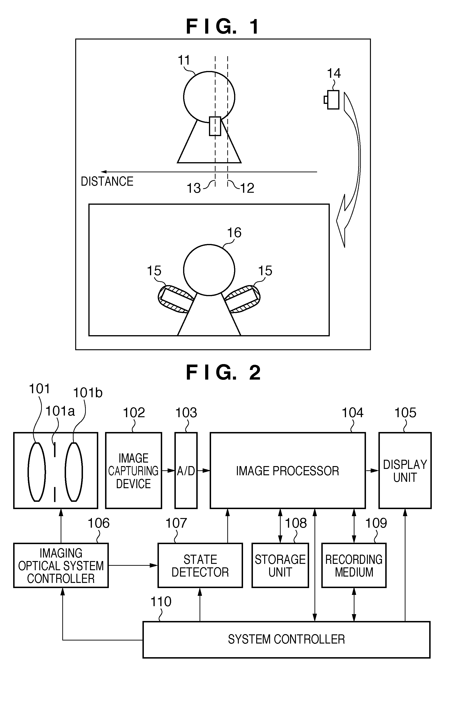
[0044]FIG. 2 is a block diagram showing the arrangement of an image capturing apparatus according to the first embodiment.

[0045]Light coming from an object (not shown) forms an image on a light-receiving surface (imaging surface) of an image capturing device 102 via an imaging optical system 101. The image capturing device 102 converts the imaged light into an electrical signal. An analog-to-digital converter (A / D) 103 converts the electrical signal output from the image capturing device 102 into a digital signal (capturing data). Note that the image capturing device 102 is a photoelectric conversion device which converts a light signal imaged on the light-receiving surface into an electrical signal for each light-receiving element.

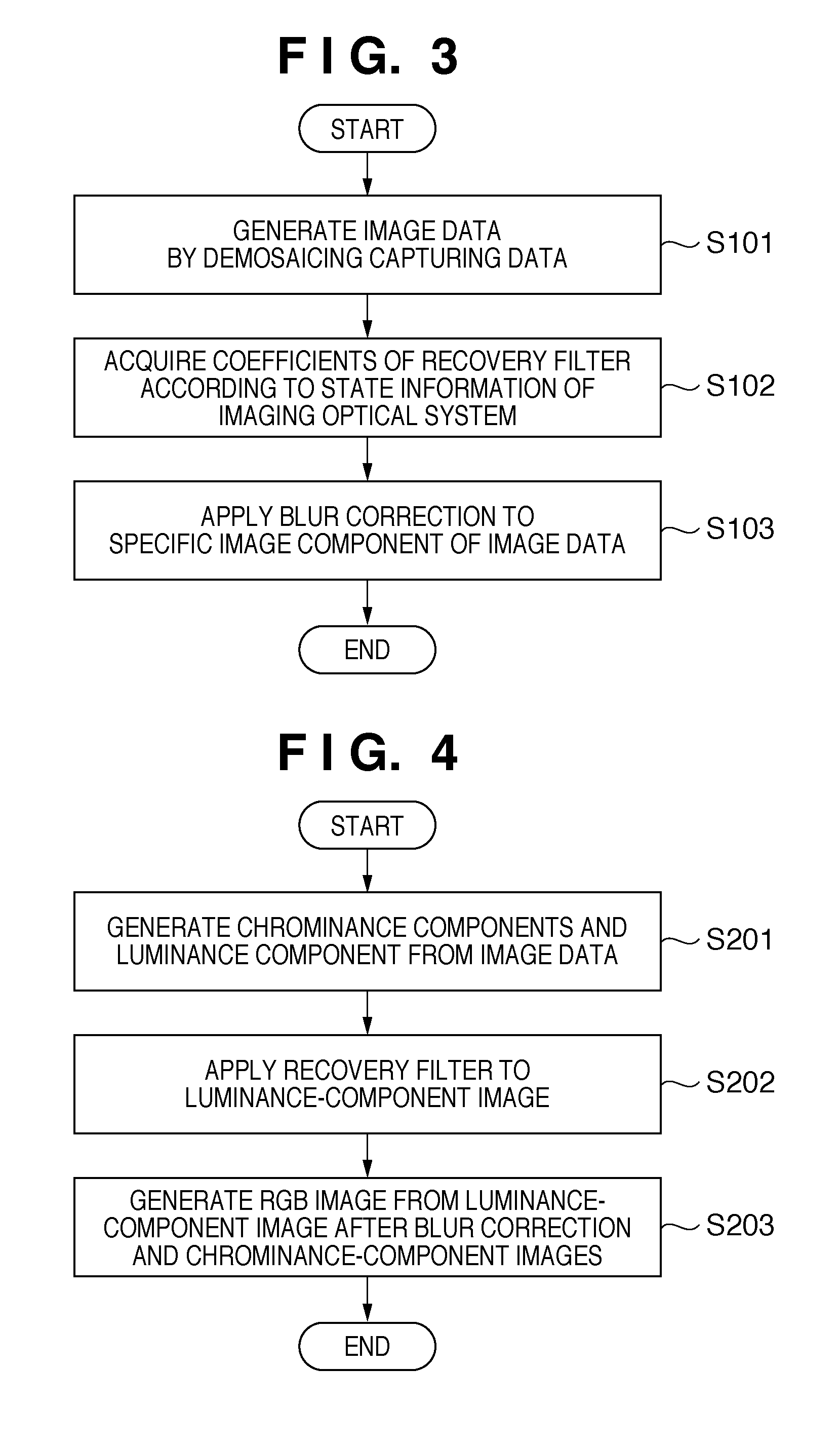
[0046]An image processor 104 stores the capturin...

second embodiment

[0060]An image process according to the second embodiment of the present invention will be described below. Note that the same reference numerals in the second embodiment denote the same parts as in the first embodiment, and a detailed description thereof will not be repeated.

[0061]The second embodiment will explain an image capturing apparatus which reduces a blur of an imaging optical system while suppressing generation of artifacts.

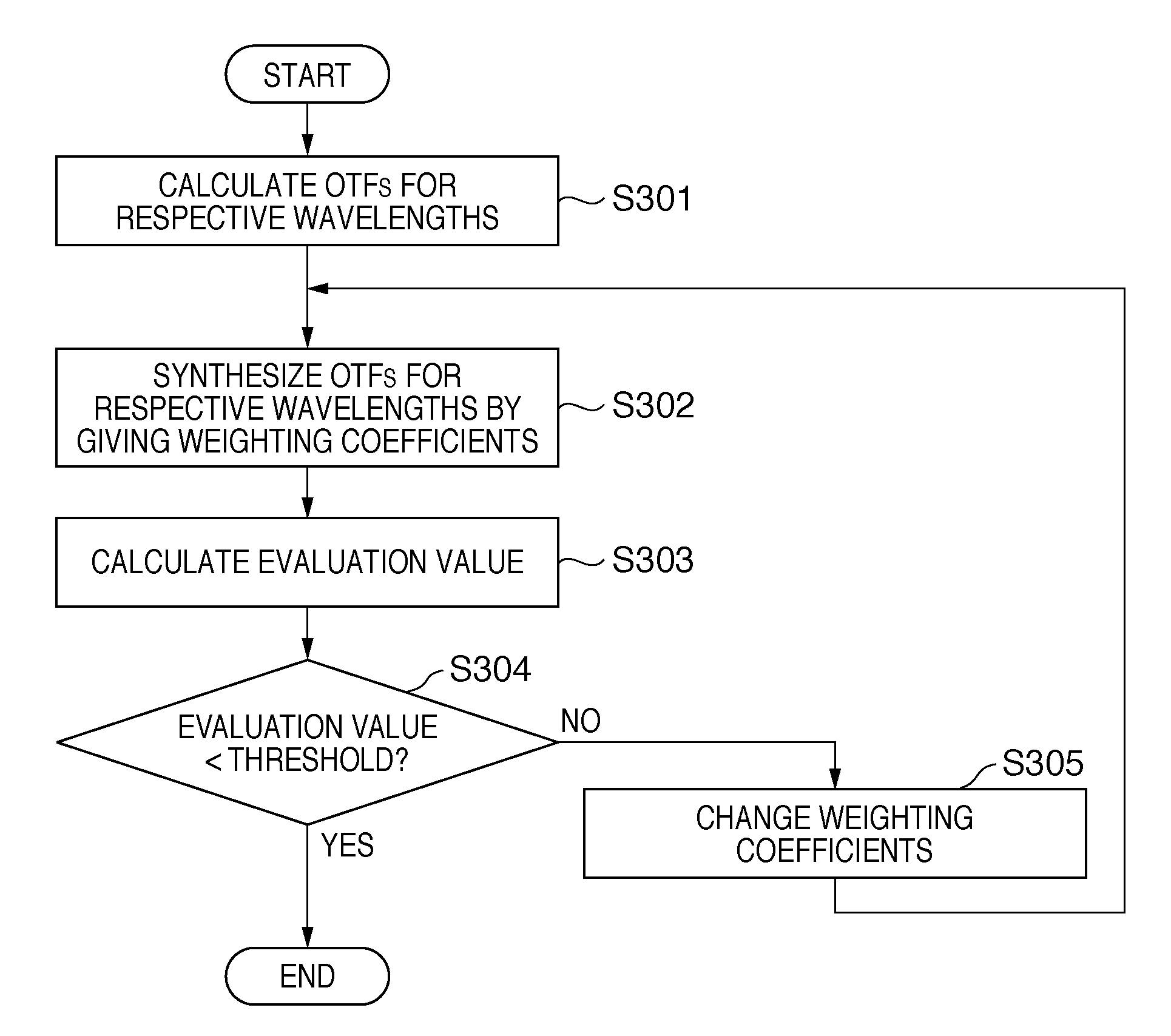
[0062]The first embodiment has explained the method of applying blur correction to a luminance-component image using the recovery filter created based on the blur characteristics of a luminance component, so as to suppress false colors generated upon correcting a blur of a defocus object. The second embodiment will explain an example in which blur characteristics as a basis of a recovery filter are calculated in consideration of the characteristics, and are applied to blur correction.

[Property of Blur Characteristics]

[0063]FIGS. 5A to 5D are graphs for...


PUM


Abstract

An image processor inputs image data from an image capturing device, and acquires blur-correction coefficients corresponding to the state of an imaging optical system which forms an image represented by light coming from an object on the image capturing device. Then, the image processor generates a target component and non-target components of blur correction from the image data, applies blur correction to the target component based on the blur-correction coefficients, and generates image data by synthesizing the target component after the blur correction and the non-target components.

Description

TECHNICAL FIELD[0001]The present invention relates to an image processing apparatus and image processing method, which correct any blur of an image caused by an imaging optical system.BACKGROUND ART[0002]An image capturing apparatus such as a digital still camera or digital video camera guides and forms an image represented by light coming from an object onto a CCD or CMOS sensor as an image capturing device via an imaging optical system including lenses. The image capturing device converts the received light into an electrical signal. Processes such as analog-to-digital (A / D) conversion and demosaicing, which convert an electrical signal into image data, are applied to this electrical signal to obtain a capturing image.[0003]Since light that reaches the image capturing device passes through the imaging optical system, the image quality of the capturing image is influenced by the imaging optical system. For example, when a high-performance lens is used, a capturing image having a hi...

Claims


Application Information

Patent Timeline
Patent Type & Authority Applications(United States)
IPC IPC(8): H04N5/217H04N9/68
CPCH04N5/23229H04N9/045H04N5/3572H04N23/80H04N25/615H04N23/843
Inventor TAMURA, NOBUHIKO
Owner CANON KK
Why Eureka
Try Eureka