Light projector and sensor

Active Publication Date: 2011-08-18
ORMON CORP
View PDF4 Cites 8 Cited by
  • Summary
  • Abstract
  • Description
  • Claims
  • Application Information

AI Technical Summary

Benefits of technology

[0023]A light projector according to one or more embodiments of the present invention is cap

Problems solved by technology

If light emission from the light source spreads over a wide angle, only a part of the li

Method used


Image

  • Light projector and sensor
  • Light projector and sensor
  • Light projector and sensor

Examples


Embodiment Construction

[0041]In the following, embodiments of the present invention will be described in detail with reference to the figures. In the figures, the same or corresponding portions are denoted by the same reference characters and description thereof will not be repeated. In embodiments of the invention, numerous specific details are set forth in order to provide a more thorough understanding of the invention. However, it will be apparent to one of ordinary skill in the art that the invention may be practiced without these specific details. In other instances, well-known features have not been described in detail to avoid obscuring the invention.

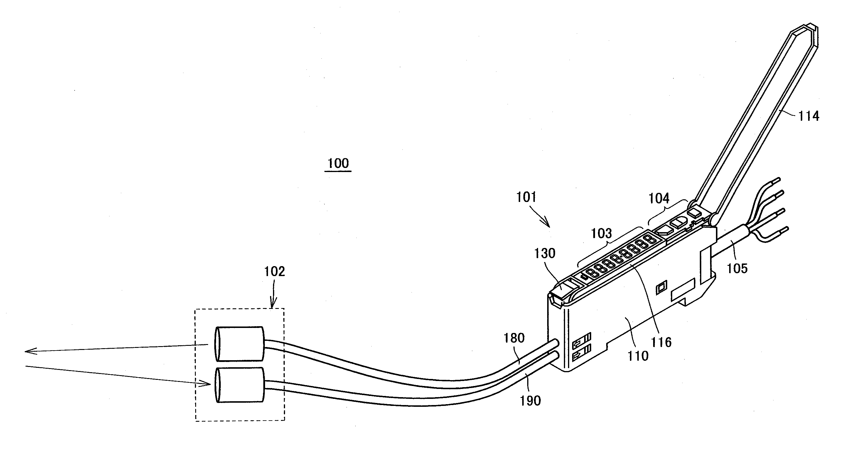
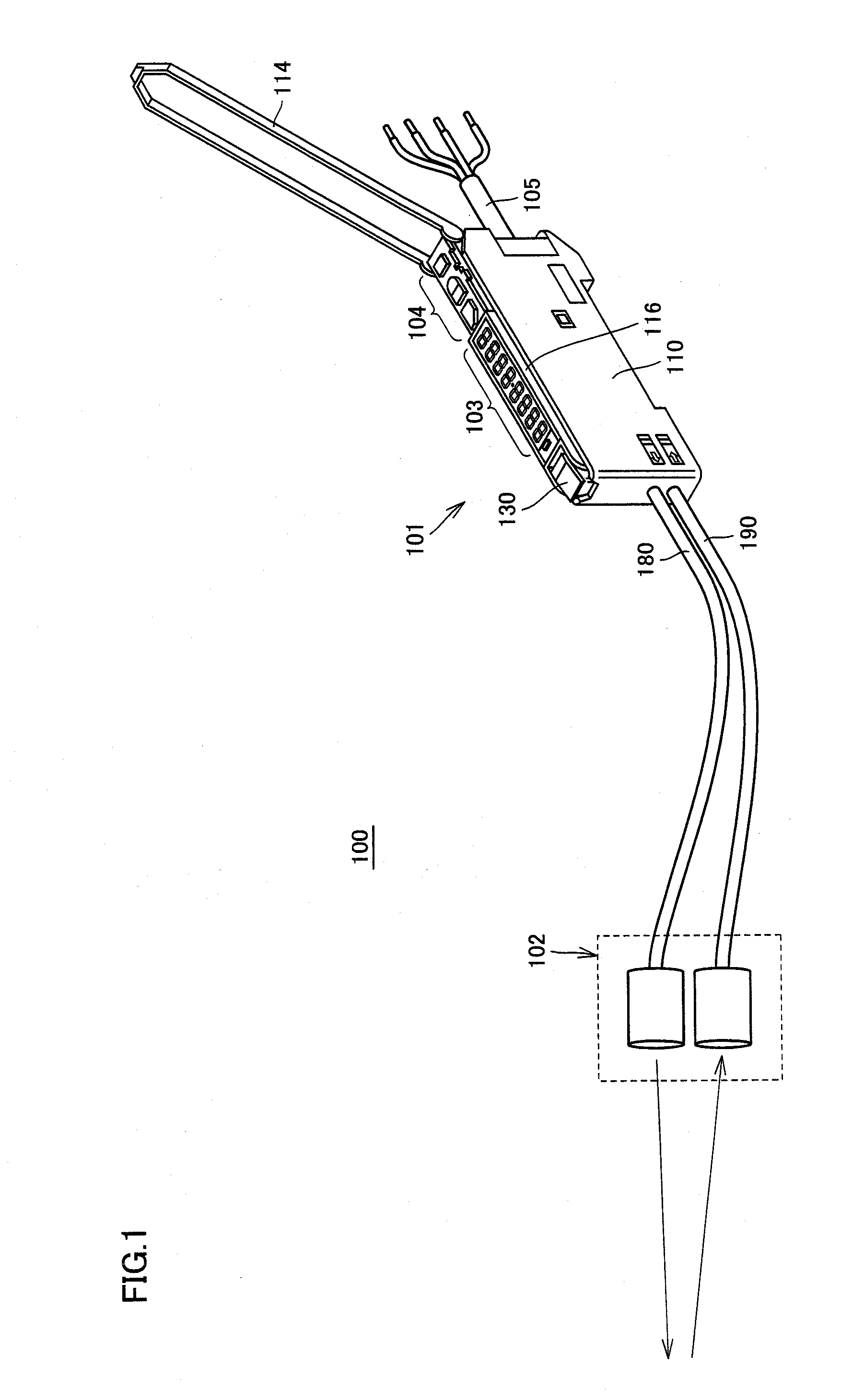
[0042]The light projector in accordance with one or more embodiments of the present invention is used, for example, in an optical fiber type photoelectric sensor utilizing a light emitting diode package (hereinafter referred to as an LED package) in which a light emitting diode chip (hereinafter referred to as an LED chip) is packaged as a light projec...


PUM


Abstract

A light projector has a light emitting device having a light emitting surface, an optical fiber having an incident end-face to which light emitted from the light emitting surface enters, and a lens arranged between the light emitting surface of the light emitting device and the incident end-face of the optical fiber. The light emitting device, the optical fiber and the lens are arranged on one optical axis. The optical fiber includes a core region as a region including a single core of uniform refractive index or a region collectively encompassing a plurality of cores having uniform refractive index. The lens converts diffused light emitted from the light emitting surface to diffused light that widens more moderately.

Description

BACKGROUND OF THE INVENTION[0001]1. Technical Field[0002]The present invention relates to a light projector and a sensor. More specifically, it relates to a light projector configured to couple light from a light source to an optical fiber, as well as to a sensor provided with the light projector.[0003]2. Background Art[0004]Conventionally, a light projector including a light source and an optical fiber and configured to couple light from the light source to an end surface of the optical fiber has been known. If light emission from the light source spreads over a wide angle, only a part of the light from the light source enters the optical fiber, resulting in low coupling efficiency. Various techniques have been proposed to improve coupling efficiency.[0005]By way of example, Japanese Patent Laying-Open No. 2005-24617 (Patent Document 1) discloses an optical transmitter capable of reducing fluctuation in transmission efficiency. In the optical transmitter, light emitted from a light...

Claims


Application Information

Patent Timeline
IPC IPC(8): H01L33/02G02B5/02
CPCG02B3/00G02B3/04F21K9/52G02B6/4206G02B6/04G02B6/4204F21K9/61G02B7/02G01J1/02
Inventor OKUNO, MOTOHARUMIYATA, TSUYOSHIKAMEDA, TAKAMASA
Owner ORMON CORP
Why Eureka
Try Eureka