Heating and dispenser system

Inactive Publication Date: 2011-08-18
ACCESS BUSINESS GRP INT LLC
View PDF76 Cites 30 Cited by
  • Summary
  • Abstract
  • Description
  • Claims
  • Application Information

AI Technical Summary

Benefits of technology

[0015]In another aspect, the heating and dispenser system includes a vibration mode, which allows a user to vibrate the surface-contacting tip assembly. Vibration of the pro

Problems solved by technology

In some applications, the applicator may be more complex and may include a reservoir for the product.
In the rolling ball example described above, the user cannot use the applicator tip with more than one product because the applicator tip is not removable from applicator.
Purchasing multiple applicators, each with their own applicator tip, can be costly because the applicator tip is usually the most expensive portion of the applicator.
Moreover, it is often difficult to clean the applicator tip separately from the applicator in this

Method used


Image

  • Heating and dispenser system
  • Heating and dispenser system
  • Heating and dispenser system

Examples


Example

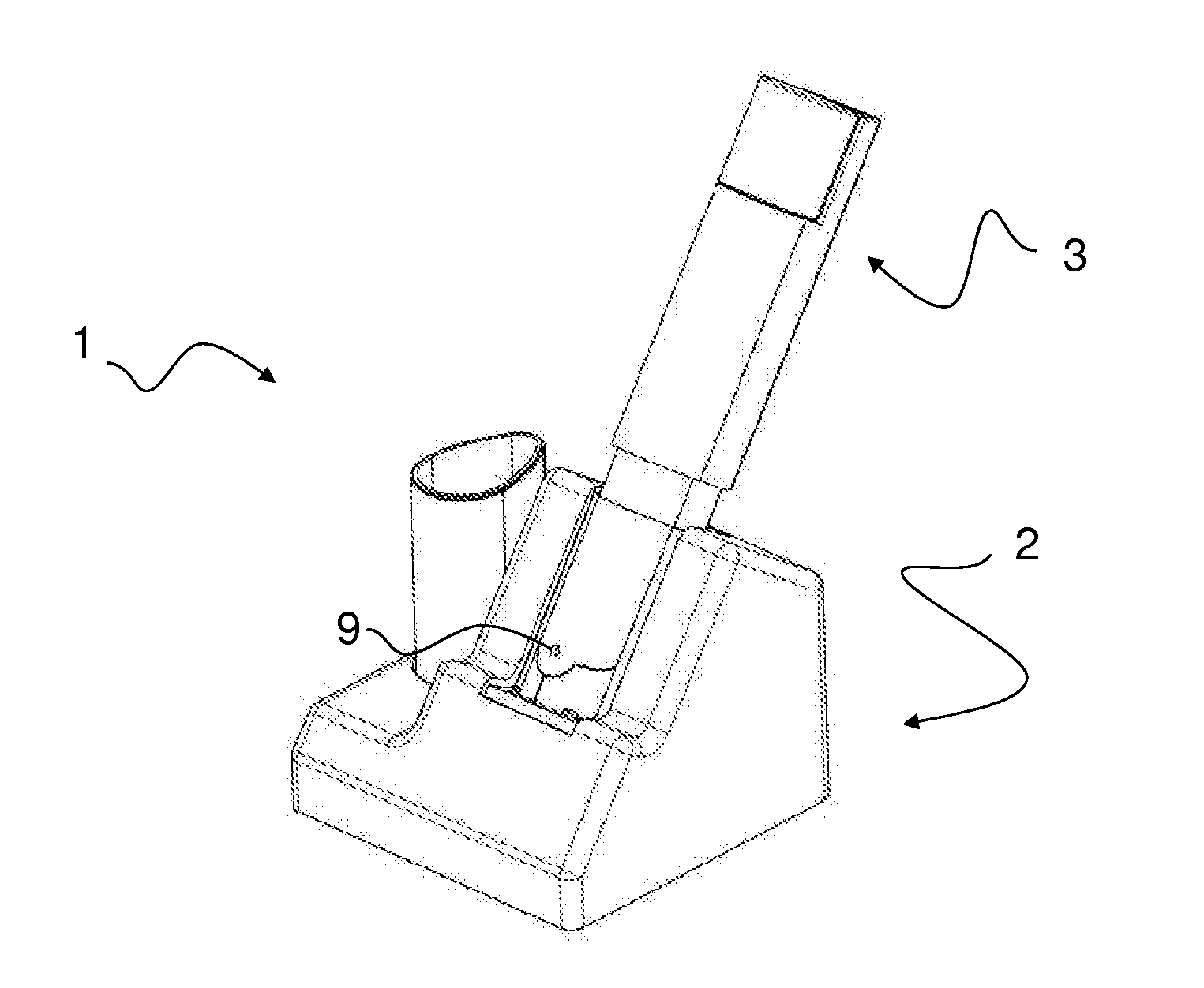
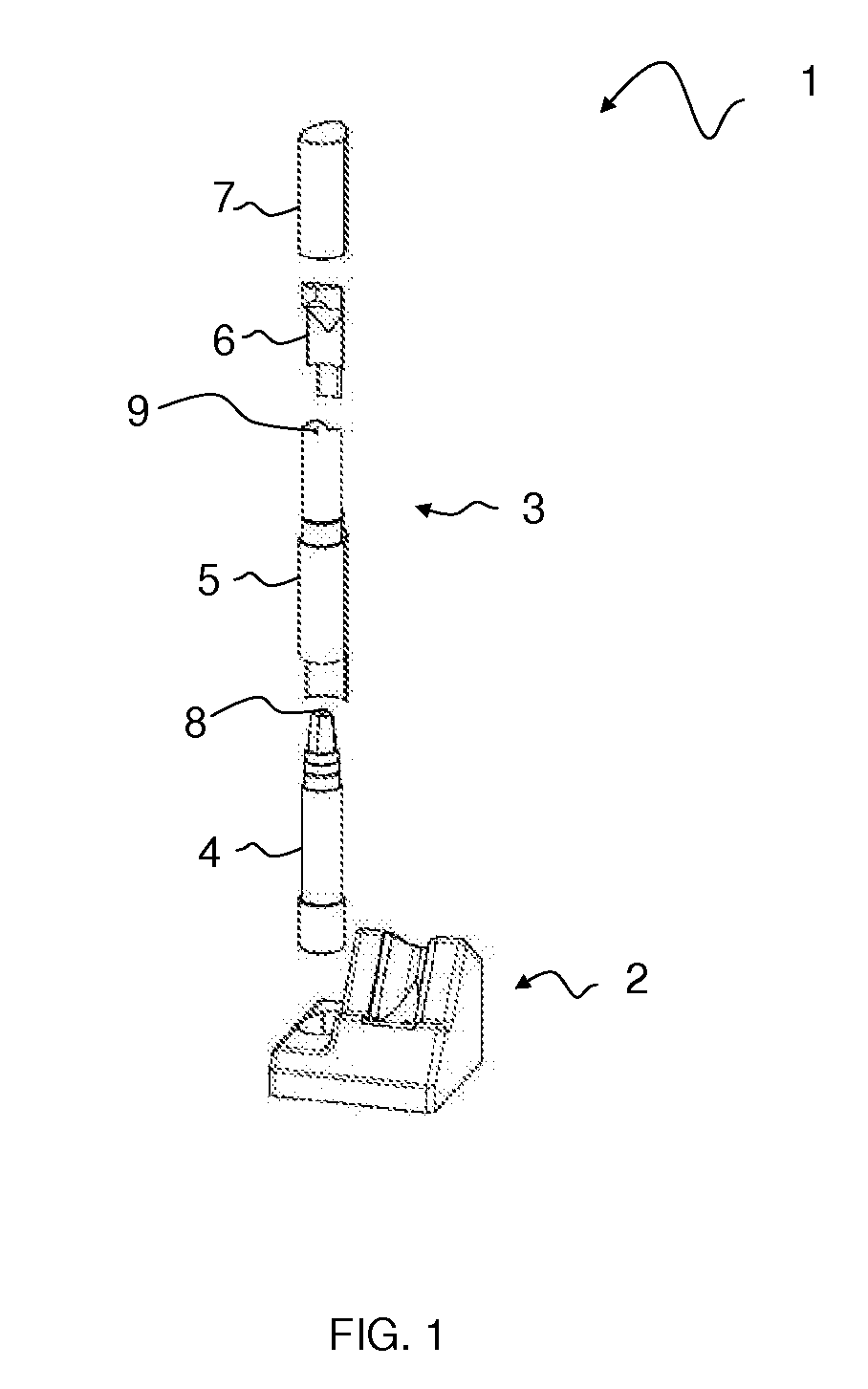
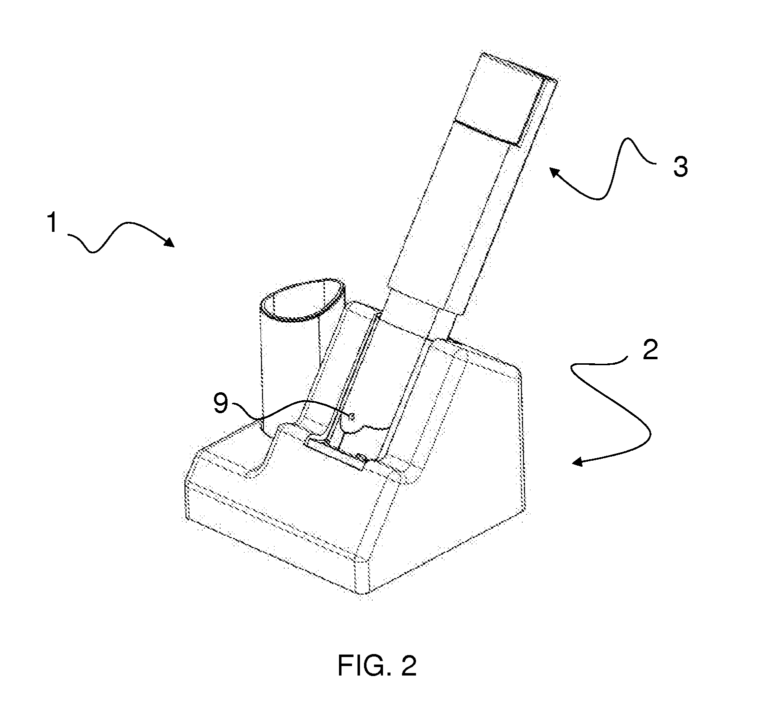
[0026]FIGS. 1-3 show an embodiment of a heating and dispenser system 1 including a base unit 2 and an applicator assembly 3. The base unit 2 may receive power from various suitable power sources, such as a wall outlet, battery, or other suitable power source. The base unit 2 includes a receptacle for storing the applicator assembly 3 and a receptacle for transferring energy to the applicator assembly 3. The receptacles may include a latching mechanism for securing the applicator assembly 3 in place. FIG. 2 shows an energy transfer configuration of the heating and dispenser system 1, and FIG. 3 shows a storage configuration of the applicator assembly 3 in the base unit 2. The base unit 2 may provide energy to the applicator assembly 3 at least in response to the applicator assembly 3 being placed in the receptacle for transferring energy. The heating and dispenser system 1 may initiate energy transfer to the applicator assembly 3 using various techniques in addition to placement of t...


PUM


Abstract

A heating and dispenser system including base unit and an applicator assembly. The applicator assembly may include an applicator tip, a dispensing module, and an applicator housing. The applicator assembly may be integral or separable, and may also house a heating module. Alternatively, the heating module may be separate from the applicator assembly. The system also includes a control system for heating and dispensing various products. The applicator assembly may be replaceable, interchangeable, or single-type for applying product to a surface. The applicator may also be constructed of materials that impact heat transfer or storage.

Description

BACKGROUND OF THE INVENTION[0001]The present invention relates to a system for dispensing and applying a personal product, and more particularly to a system for dispensing the personal product and applying the product with a heated applicator.[0002]A wide variety of serums, salves and other health and beauty products are available for topical application. In some applications, these products are applied simply by hand. With many products, however, an applicator is available to assist the user in applying the product. Applicators are available in a variety of different types. Simple applicators may utilize a brush or foam pad to apply the product. In some applications, the applicator may be more complex and may include a reservoir for the product. One conventional applicator includes a rolling ball for applying the product. In a typical rolling ball applicator, the rolling ball is positioned in the neck of a product reservoir with a portion exposed on the exterior of the applicator. ...

Claims


Application Information

Patent Timeline
IPC IPC(8): A46B11/08B67D7/82
CPCA45D34/04A45D2200/155A45D2034/002A61F7/0085A61F2007/0071A61M35/003B05C1/06
Inventor BYLSMA, RICHARD B.MORK, STEVE O.BAARMAN, DAVID W.NIEZGODA, THOMAS A.LEVERETT, JESSE
Owner ACCESS BUSINESS GRP INT LLC
Why Eureka
Try Eureka