[0006]The invention provides a film stretcher that is able to easily reduce the thickness of a film without a nonuniform stretch or a neck-in.
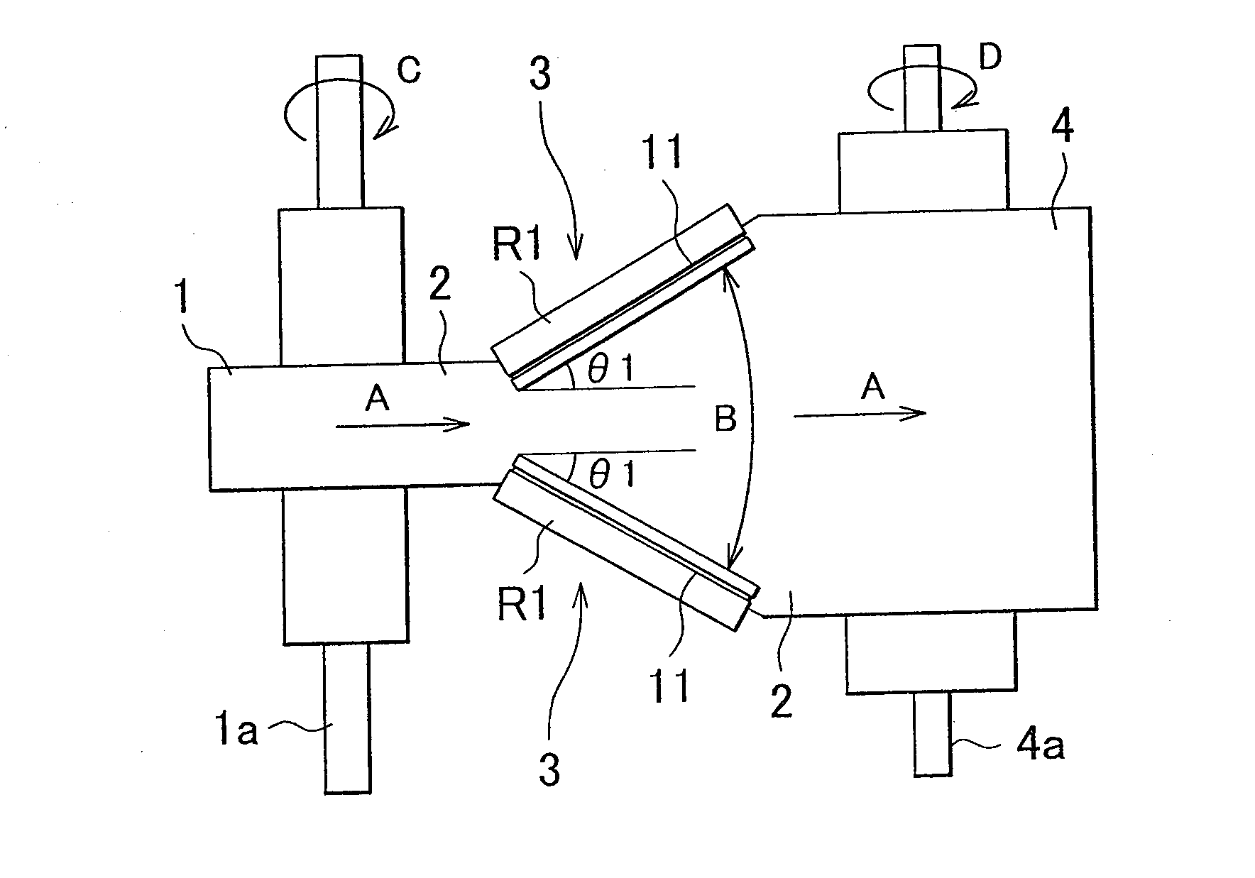
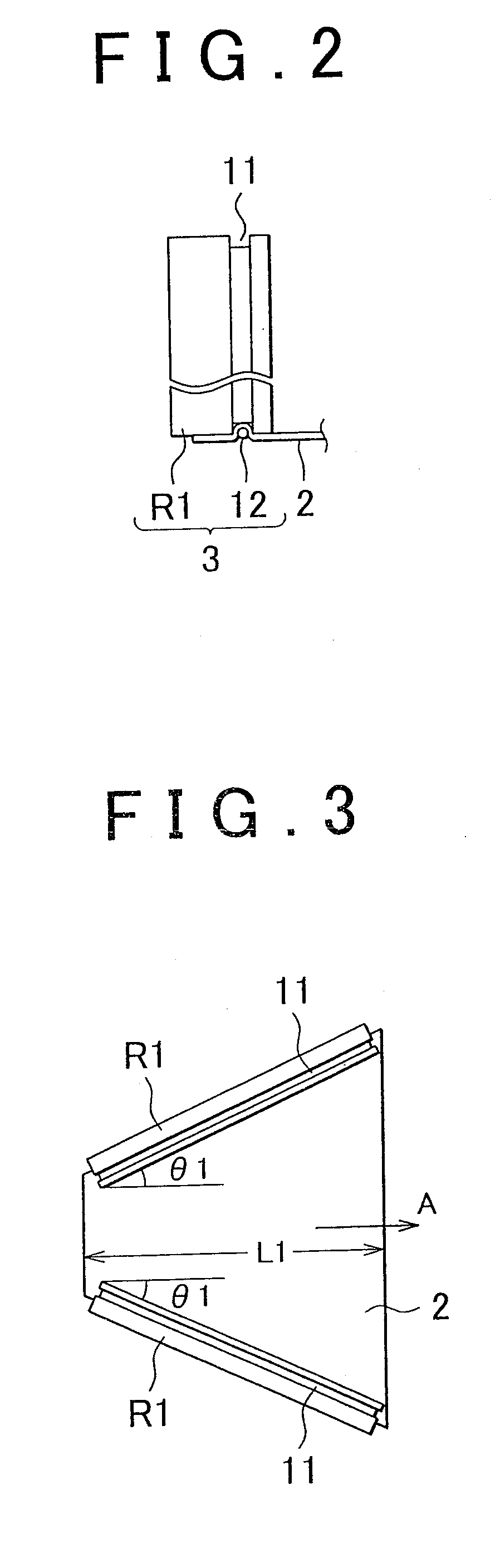
[0007]An aspect of the invention relates to a film stretcher that transports a film material in a predetermined transport direction while holding an end of the film material in a width direction of the film material to stretch the film material in the width direction. The film stretcher includes a holding unit that includes a stretching roll having an annular groove formed on an outer periphery of the stretching roll and a holding wire material that is fitted in the annular groove over a predetermined rotation angle range of the annular groove in a circular arc shape so that the end of the film material in the width direction of the film material is pinched, wherein the stretching roll is inclined so as to open toward a downstream side in the transport direction of the film material, and the holding unit transports the film material in the transport direction while pinching the film material using the stretching roll and the holding wire material, whereby the film material is stretched in the width direction. The film material may be a resin used for a separation membrane, an
optical film, a packaging material, a clothing material, a heat insulating material, an insulating material, or the like. The resin may be, for example,
polyethylene,
polytetrafluoroethylene,
polyamide,
polypropylene,
polyvinyl alcohol,
polyvinyl chloride resin, nylon (product name),
polystyrene,
polyester or
polyethylene terephthalate. The holding wire material may be a
metal, such as stainless steel, iron, aluminum,
tungsten and
brass, a resin, such as nylon (product name), vinylon,
polyester,
polyethylene,
polypropylene,
polytetrafluoroethylene and
acrylic resin, a wire material made of carbon
fiber, hemp or cotton, or the like. Particularly, the holding wire material may be formed of a wire, a belt, or the like, made of any one of these wire materials. The holding unit may be provided at least on one of the ends of the film material in the width direction of the film material. With the above configuration, it is possible to provide a film stretcher that is able to easily reduce the thickness of the film material without a nonuniform stretch or a neck-in.
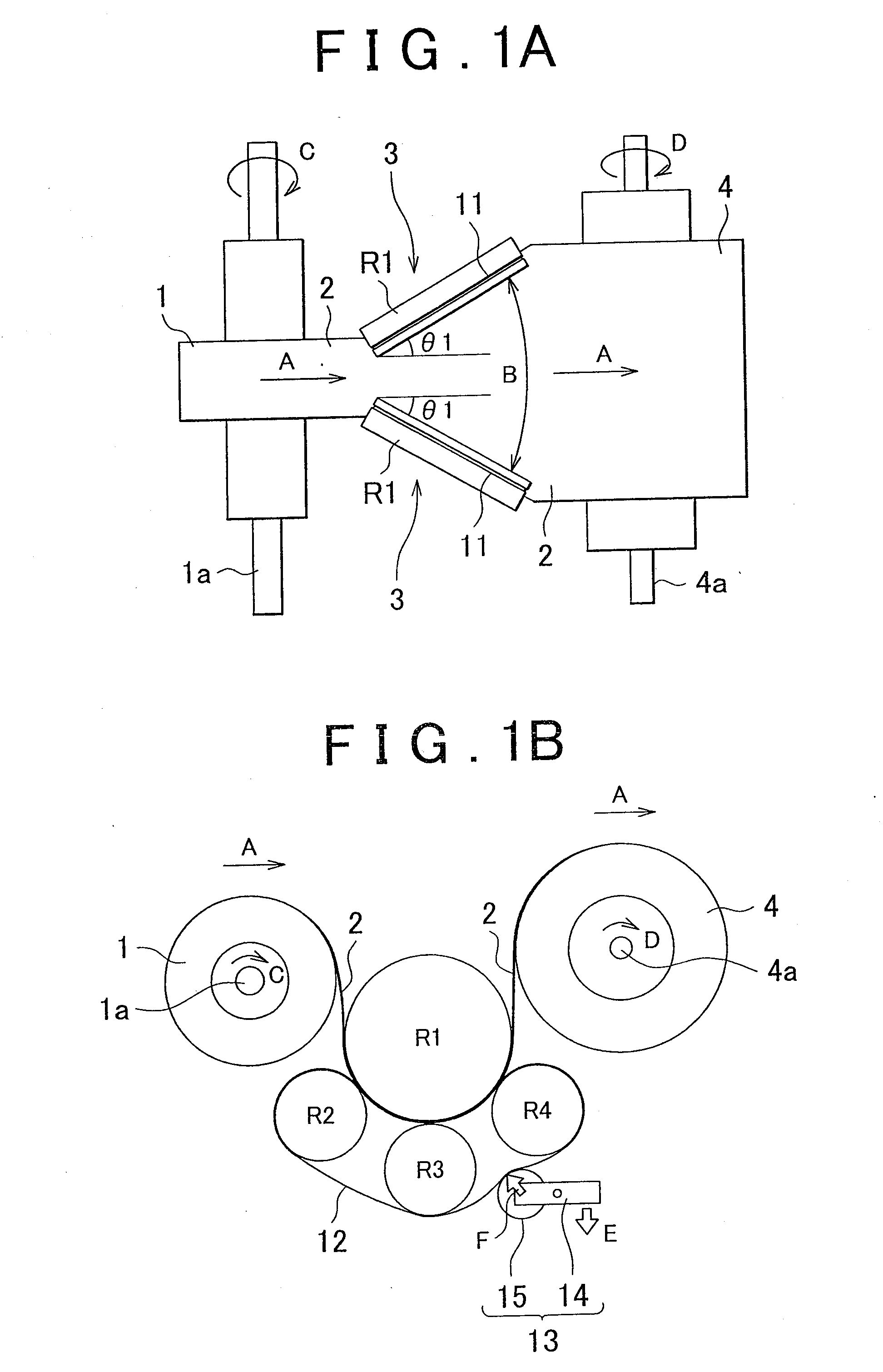
[0010]In the above aspect, the holding wire material may be an endless holding wire material that is wound around a plurality of transport rolls of which rotation axes are arranged along a concentric circle of the stretching roll at a predetermined angular interval, and the plurality of transport rolls may be arranged so that outer
peripheral surfaces of the respective transport rolls face the annular groove with the end of the film material in the width direction of the film material interposed therebetween. With the above configuration, by changing the positions (angles) of the transport rolls with respect to the stretching roll, it is possible to control stretching start and end positions in the stretching locus. Thus, it is possible to vary a sketching speed (
magnification ratio) within a stretching section.
[0011]In the above aspect, the film stretcher may further include a tensioner that is located between any two adjacent transport rolls from among the plurality of transport rolls, and that presses the holding wire material from an outer
peripheral side of the holding wire material to adjust tension of the holding wire material, whereby the tensioner may adjust the pinching force. With the above configuration, the tension of the endless wire may be adjusted, and the thickness of the film material may be tracked while ensuring a certain holding force applied to the film material. Thus, it is possible to stretch a thin film. The tensioner is able to suppress a decrease in pinching force of the holding wire material due to a reduction in thickness of the film material in accordance with a stretch of the film material.
[0013]In the above configuration, the stretching roll may be arranged at a predetermined
camber angle. With the above configuration, it is possible to set a predetermined stretching locus by setting a predetermined
camber angle.
