Non-Backdrivable Gear System

a gear system and non-backdriving technology, applied in the direction of gearing details, gearing, mechanical equipment, etc., can solve the problems of unnecessarily complex a pair of pinned or bolted or welded gears, unreliable and reliable transmission, and the inability to manufacture separate gears in one pi

Active Publication Date: 2011-08-18
KINATECH LLC
View PDF9 Cites 6 Cited by
  • Summary
  • Abstract
  • Description
  • Claims
  • Application Information

AI Technical Summary

Benefits of technology

The present invention addresses the above drawbacks of the prior art by providing simple and low-cost gearbox systems that can be driven in a forward and reverse direction through an input motor shaft...

Problems solved by technology

Two gears on the same shaft with different pitch diameters or different numbers of teeth are difficult to manufacture in one piece, and unnecessarily complex as a pair of pinned or bolted or welded gears.
Separate gears fixed together are not as robust as a continuous metal cross section.
Thus, while self-locking or ...

Method used


Image

  • Non-Backdrivable Gear System
  • Non-Backdrivable Gear System
  • Non-Backdrivable Gear System

Examples


example 1

Output Ring Gear System

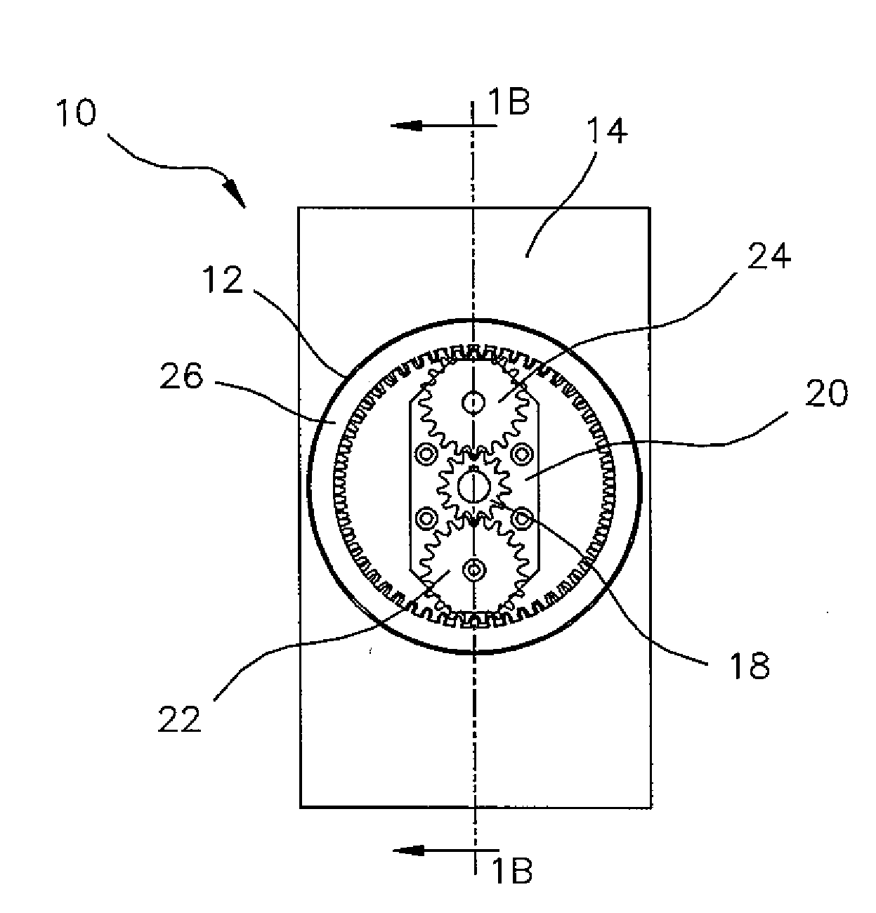
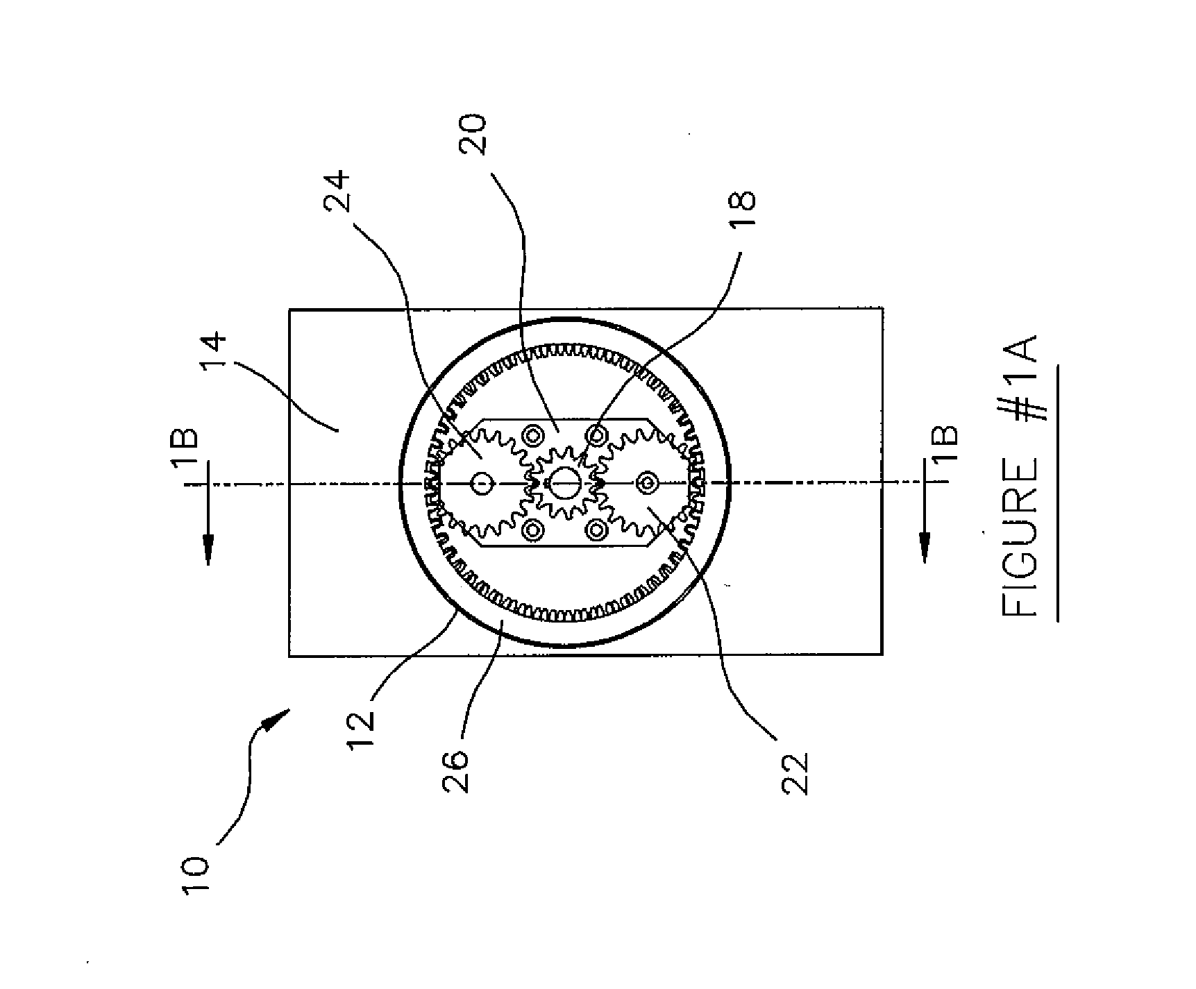
A gear system was produced with the fixed ring 12 having 53 teeth and the output ring 26 having 51 teeth producing an approximate 25 to 1 gear ratio. The sun gear 18 was produced with 13 teeth and the planet gear 24 was produced with 20 teeth 24′ producing an additional ratio of 1.5 to 1 yielding an overall ratio of approximately 130 to 1. The design also allows for rotating the spider support frame 20 and allowing the sun gear 18 to idle. This shift yields an end ratio of 67 to 1 (input torque is applied directly to the spider frame 20 with sun gear 18 eliminated).

It is understood that the tooth numbers and ratios listed above are an example and are therefore not to be construed as limiting the invention. It will be appreciated to those skilled in the art that the gearing concept of Example 1 can be scaled up or down in size of gears or number of teeth or number of gears or gear configuration.

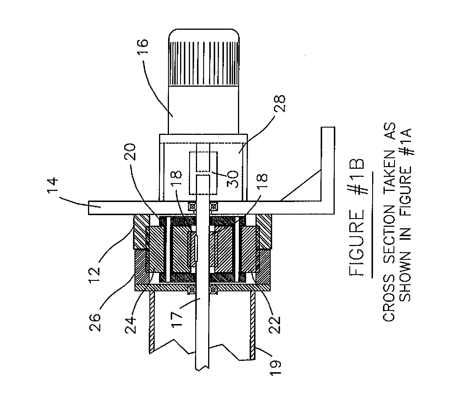
FIG. 1B shows motor 16 mounted on a housing 28 to accommodate a sha...


PUM


Abstract

A self-locking non-backdrivable gear system in one embodiment includes an input spur gear mounted to a drive shaft, the input spur gear positioned in meshing engagement with a ring gear on which is mounted at least one planet locking gear which rotates with the ring gear and rotates on its own mounting. The planet locking gear meshes with a fixed spur gear and an output spur gear connected to a bi-rotational load bearing device. The fixed and output gears have different number of teeth and will lock in place with the planet gear should a rotational force be applied to the load bearing device in the absence of a rotational force at the drive shaft.

Description

BACKGROUND OF THE INVENTIONThe present invention generally relates to the field of gear design, and more particularly relates to gear systems which are self-locking and non-backdrivable.An example of prior art gear systems which are self-locking and non-backdrivable include harmonic gear assemblies which employ flexible metal bands or flexible metal cups that have gear teeth machined into their outer periphery. These bands or cups are forcibly deformed with inner oval cams that employ many pins or balls or bearings, against fixed ring type spur gears. These configurations allow for the smooth movement of the flex cup or flex band, while only engaging several teeth at a minimum of one position, but usually two or three positions. The bi-lobular or tri-lobular cams are rotated one full revolution which only engages a small number of teeth in the fixed outer ring gear. This creates a gear ratio relative motion, while locking the band or cup to the fixed outer ring gear.Other prior art ...

Claims


Application Information

Patent Timeline
IPC IPC(8): F16H1/28
CPCF16H1/003
Inventor KOCHAN, STEPHEN JOHN
Owner KINATECH LLC
Why Eureka
Try Eureka