
Exhaust Gas Treatment Device

Active Publication Date: 2011-08-25
PUREM GMBH
View PDF12 Cites 17 Cited by
  • Summary
  • Abstract
  • Description
  • Claims
  • Application Information

AI Technical Summary

Benefits of technology

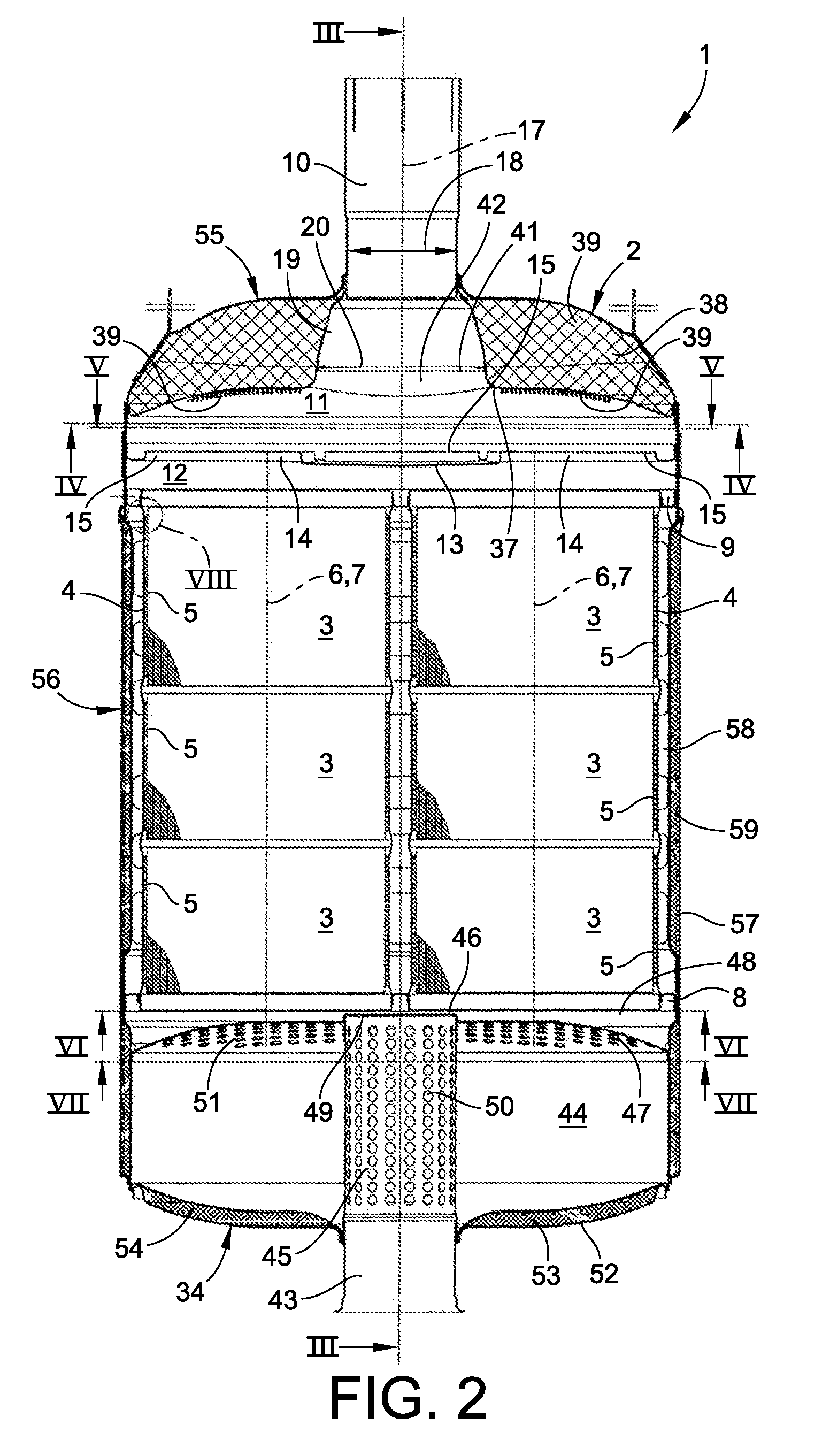
[0007]Embodiments of the invention are based on the general idea of arranging a separating bottom in the housing, which constructionally separates an outlet chamber from a collecting chamber, wherein passage openings formed in the separating bottom fluidically connect the outlet chamber with the collecting chamber. In addition, collars protruding into the outlet chamber are formed on the separating bottom which enclose the passage openings. Through the proposed design water that can enter the housing via an outlet pipe fluidically connected with the outlet chamber cannot easily enter the collecting chamber through the passage openings of the separating bottom. For the collars, which enclose the passage openings form barriers that cannot be easily breached by water. Thus, should water enter the housing via the outlet pipe it is able to get as far as to the outlet chamber, but not beyond. In particular, because of this, the water does not reach as far as the respective exhaust gas treatment element and particularly not as far as to the associated bearing mat either. In this manner, the risk of water entering the housing contacting the bearing mat can be effectively reduced.
[0008]According to an advantageous embodiment, the separating bottom can have a closed region axially aligned with the outlet pipe, whose area is larger than the cross-sectional area of the outlet pipe. Through this it is achieved that water directly dripping from the outlet pipe in the axial direction strikes the closed region, but no passage opening in any event. Thus it can be prevented that water, which directly drips off the outlet pipe, drips through the passage openings.
[0009]According to another embodiment, the outlet pipe can comprise a funnel flaring towards the outlet chamber arranged in the housing or merge into such. The funnel reduces the flow resistance at the transition to the outlet pipe and results in an acceleration of the exhaust gas flow.
[0011]With another further development a sensor, more preferably a NOX-sensor, can be attached in the region of the outlet pipe or in the region of the funnel namely in such a manner that the sensor between the ends of the outlet pipe or the funnel protrudes into the interior of the outlet pipe or of the funnel. The positioning of the sensor in this position makes possible for example a reliable monitoring of the exhaust gas treatment device.
[0012]According to a particularly advantageous further development it can now be provided to fasten the sensor to the housing by means of a sensor bush, wherein this sensor bush penetrates a housing wall and an outlet pipe wall or a funnel wall. Through the sensor bush the sensor protrudes into the interior of the outlet pipe or of the funnel. Practically, this sensor bush can now be equipped with an annular circumferential outer groove in the interior of the outlet pipe or of the funnel. Insofar as on the inside of the outlet pipe or of the funnel along the outer pipe wall or the funnel wall water drains off, this does not directly strike the sensor but the sensor bush, as a result of which the risk of a contamination of the sensor with water is reduced. Insofar as the water would like to continue flowing along the sensor bush in the direction of the sensor the optionally provided outer groove ensures that the water can only spread as far as to the outer groove, then collects therein and drains off from there due to the force of gravity. Insofar water contacting the sensor is effectively avoided.

Problems solved by technology

The funnel reduces the flow resistance at the transition to the outlet pipe and results in an acceleration of the exhaust gas flow.

Method used


Image

  • Exhaust Gas Treatment Device
  • Exhaust Gas Treatment Device
  • Exhaust Gas Treatment Device

Examples


Embodiment Construction

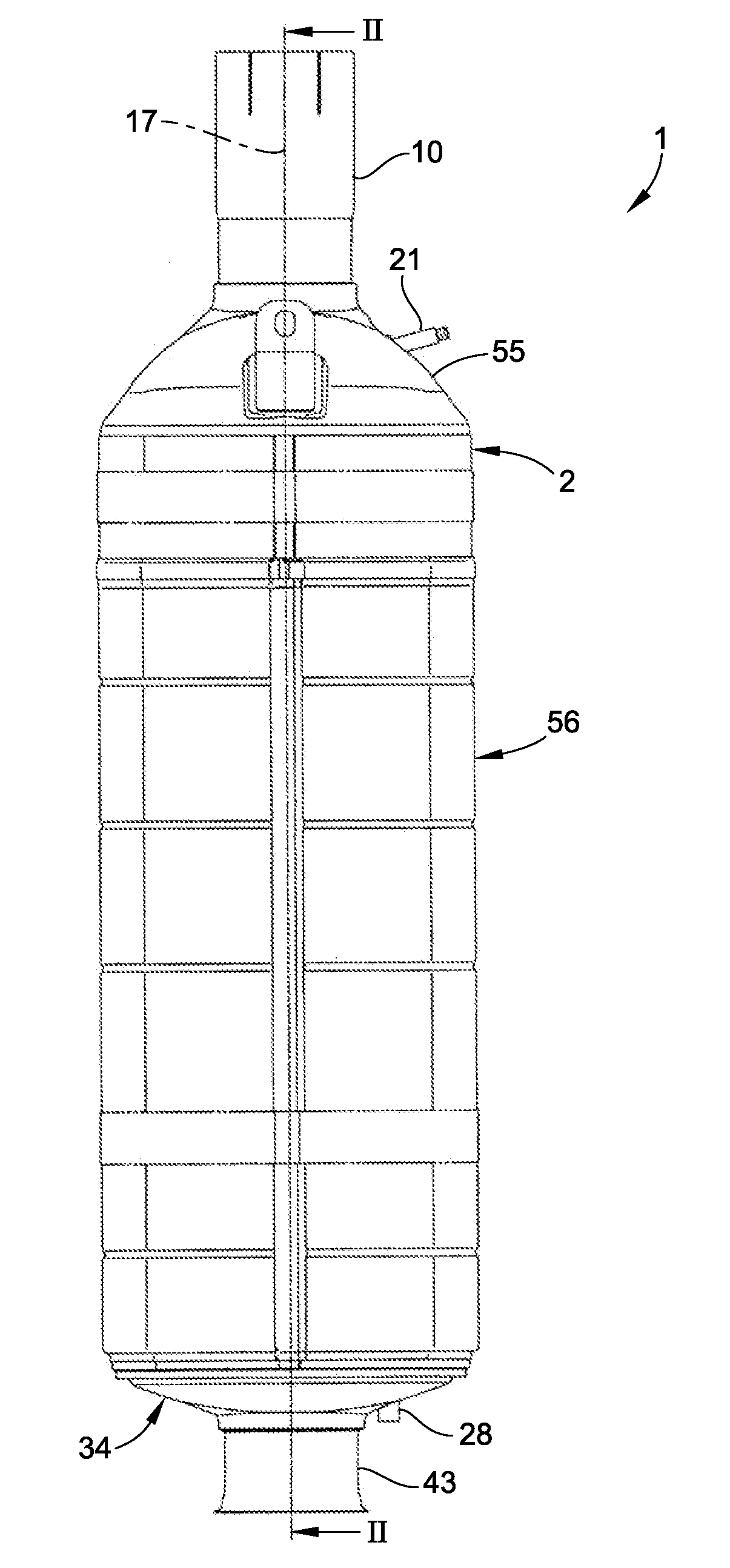
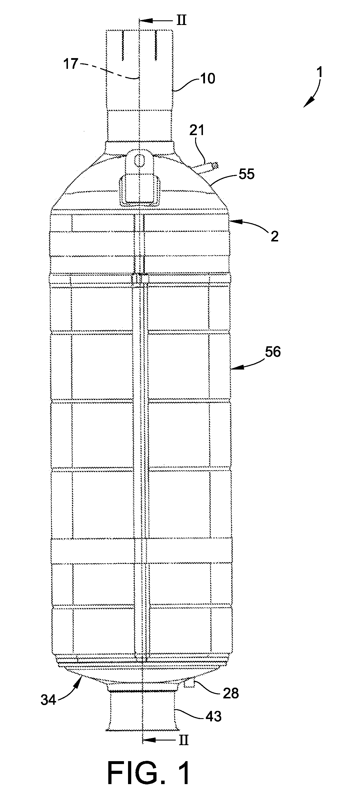
[0025]Corresponding to the FIGS. 1 to 5 an exhaust gas treatment device 1 comprises a housing 2 as well as at least one exhaust gas treatment element 3. The exhaust gas treatment device 1 serves for use in an exhaust system of an internal combustion engine, which more preferably can be arranged in a road vehicle. The exhaust gas treatment device 1 preferably is a catalytic converter or a particle filter, preferentially in combination with a silencer. As catalytic converters, NOX-storage catalytic converters or SCR-catalytic converters are preferably considered. The particle filter preferably is a soot filter. Accordingly, the at least one exhaust gas treatment element 3 preferably is a catalytic converter element, more preferably a NOX-storage catalytic converter element or an SCR-catalytic converter element or a particle filter element, more preferably a soot filter element.

[0026]In the example shown according to FIG. 2 a total of six exhaust gas treatment elements 3 are provided. ...


PUM


Abstract

The present invention relates to an exhaust gas treatment device for an exhaust system of an internal combustion engine, more preferably of a road vehicle with a housing, in which at least one exhaust gas treatment element is arranged and mounted by means of a bearing mat and with an outlet pipe which is fluidically connected to an outlet chamber formed in the housing. The risk of a contamination of the bearing mat with water can be reduced with a separating bottom which is arranged in the housing and separates the outlet chamber from a collecting chamber. The separating bottom includes several passage openings through which the outlet chamber is fluidically connected to the collecting chamber and which are each enclosed by a collar protruding into the outlet chamber.

Description

CROSS-REFERENCE TO RELATED PATENT APPLICATIONS[0001]This patent application claims the benefit of German Application No. 10 2010 008 999.0, filed Feb. 24, 2010, the entire teachings and disclosure of which are incorporated herein by reference thereto.FIELD OF THE INVENTION[0002]The present invention relates to an exhaust gas treatment device for an exhaust system of a combustion engine, particularly of a road vehicle.BACKGROUND OF THE INVENTION[0003]Exhaust gas treatment devices, such as catalytic converters, particle filters and silencers as well as any combinations thereof, usually comprise a housing in which at least one exhaust gas treatment element, such as for example a catalytic converter element or a particle filter element, is arranged. Insofar as ceramic exhaust gas treatment elements are employed, these are usually mounted in the housing by means of a bearing mat.[0004]With certain installation situations, particularly upon a positioning of the exhaust gas treatment devic...

Claims


Application Information

Patent Timeline
IPC IPC(8): F01N13/08
CPCF01N3/005F01N3/2853Y02T10/20F01N2490/08F01N2560/026F01N13/008Y02A50/20Y02T10/12
Inventor WERNI, MARCUSSAUER, ANDREAS
Owner PUREM GMBH
Learn More