Substrate for mounting light-emitting element and light-emitting device

a technology of light-emitting elements and substrates, which is applied in the direction of layered products, transportation and packaging, chemical instruments and processes, etc., can solve the problems of difficult products to employ such a method, easy corrosion of silver, and deterioration of optical reflectance, so as to prevent corrosion of silver, maintain luminous efficiency, and prevent deterioration of reflection layer reflectan

Inactive Publication Date: 2011-08-25
ASAHI GLASS CO LTD
View PDF5 Cites 30 Cited by
  • Summary
  • Abstract
  • Description
  • Claims
  • Application Information

AI Technical Summary

Benefits of technology

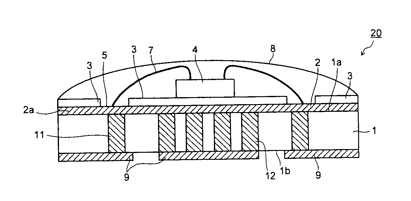
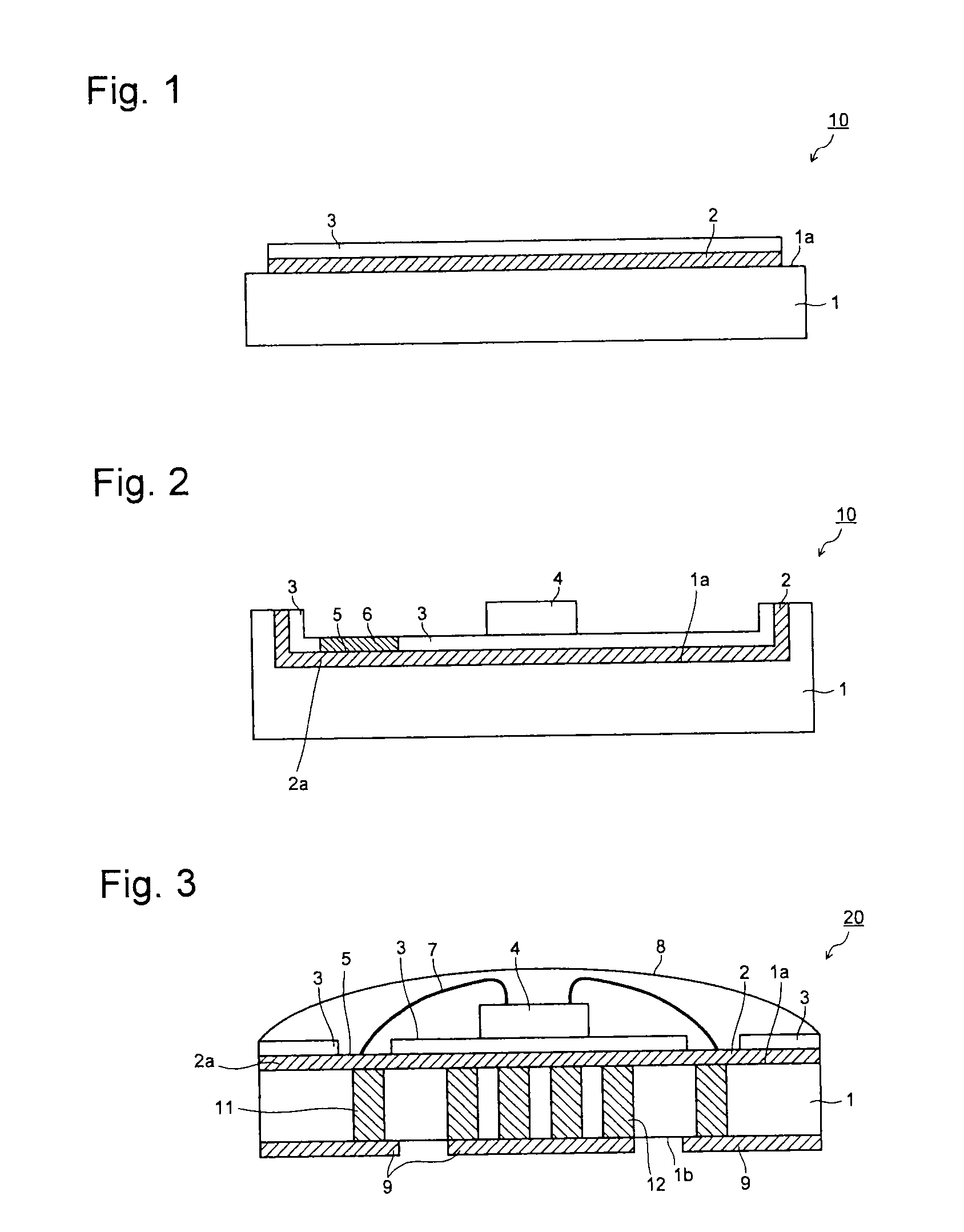
[0015]In the substrate for mounting a light-emitting element of the present invention, the reflection layer containing silver is covered by the vitreous insulating layer, whereby it is possible to prevent a change (a change by corrosion) such as oxidation or sulfurization of the reflection layer, and it is possible to prevent deterioration of the reflectance of the reflection layer.
[0016]Further, in the present invention, the quantitative relations between the alkali metal oxide and Al2O3, and between SiO2 and Al2O3, in the glass constituting the vitreous insulating layer, are defined, whereby a silver colloid tends to be hardly formed even if silver contained in the reflection layer diffuses into the glass, and it is thereby possible to prevent silver coloring.
[0017]In the light-emitting device of the present invention, the above-described substrate for mounting a light-emitting element is used, whereby the reflectance of the reflection layer tends to hardly deteriorate, and it can be expected to maintain the luminous efficiency for a long period of time.

Problems solved by technology

However, silver is likely to be corroded, and if it is left to stand, a compound such as Ag2S is likely to be formed, whereby the optical reflectance tends to deteriorate.
However, by such a method, moisture or a corrosive gas is likely to enter into the resin or from the interface between the silver reflection layer and the resin, whereby the silver reflection layer is corroded as the time passes, and thus it has been difficult to employ such a method for products which are required to have a reliability for a long period of time.
However, the glass layer formed by this method undergoes a color change from yellow to brown by a reaction with silver during the firing, whereby the reflectance tends to deteriorate, and thus, such a method has been inadequate for application to products.
On the other hand, as a method to increase the reflectance without using a silver reflection layer, it has been proposed to use an alumina material or the like having a high reflectance, but firing at a high temperature exceeding 1,000° C. is required, and thus there has been a problem that the load on the production process is substantial.

Method used


Image

  • Substrate for mounting light-emitting element and light-emitting device
  • Substrate for mounting light-emitting element and light-emitting device

Examples


examples

[0083]Now, the present invention will be described in further detail with reference to Examples.

[0084]In each of Examples 1 to 59, glass to form a vitreous insulating layer was prepared. That is, glass raw materials were blended and mixed so that the respective components of SiO2, B2O3, ZnO, Al2O3, MgO, CaO, SrO, BaO, R2O (Li2O, Na2O, K2O), TiO2 and ZrO2 would constitute a composition (mol %) shown in Tables 1 to 7, and this raw material mixture was put into a platinum crucible and melted at from 1,500 to 1,600° C. for 60 minutes. Then, the molten state glass was cast and cooled. The obtained glass was ground for from 20 to 60 hours by a ball mill made of alumina by using water as a solvent to obtain a glass powder.

[0085]The average particle size D50 of the obtained glass powder was measured by means of SALD2100 manufactured by Shimadzu Corporation, and in each case, D50 was within a range of from 1 to 3 μm. Further, the softening point Ts (unit: ° C.) of each glass powder was measu...


PUM


Abstract

To provide a substrate for a light-emitting device, which is provided with a reflection layer having a high optical reflectance and being less susceptible to deterioration of the reflectance due to corrosion and which has an improved light extraction efficiency, and a light-emitting device employing such a substrate.A substrate for mounting a light-emitting element, which comprises a substrate main body having a mounting surface on which a light-emitting element is to be mounted, a reflection layer formed on a part of the mounting surface of the substrate main body and containing silver to reflect light emitted from the light-emitting element, and a vitreous insulating layer formed on the reflection layer, wherein the vitreous insulating layer contains a glass comprising, as its constituting components, at least SiO2, at least one of Al2O3 and B2O3, and an alkali metal oxide (containing at least one member selected from Li2O, Na2O and K2O), wherein by contents as represented by mol % based on oxides of the above components, (Li2O+Na2O+K2O)—Al2O3 is from −20 to 1.5%, and SiO2+3×Al2O3 is at most 90%.

Description

TECHNICAL FIELD[0001]The present invention relates to a substrate for mounting a light-emitting element and a light-emitting device, particularly to a substrate for mounting a light-emitting element capable of preventing deterioration of the reflectance, and a light-emitting device employing it.BACKGROUND ART[0002]In recent years, along with a tendency to high brightness and whitening of a light-emitting element such as a light-emitting diode (LED) element, a light-emitting device employing a light-emitting element has been used for illumination, backlights of various displays or large-sized liquid crystal TVs, etc. The substrate for mounting a light-emitting element, to mount a light-emitting element, is usually required to have a high reflectivity to efficiently reflect light emitted from the element.[0003]Accordingly, it has been heretofore attempted to provide a reflection layer on the substrate surface for the purpose of reflecting light emitted from a light-emitting element to...

Claims


Application Information

Patent Timeline
Patent Type & Authority Applications(United States)
IPC IPC(8): H01L33/60B32B15/04
CPCH01L33/486H01L33/60H01L2224/48091H01L2224/48227H01L2224/45144H01L2924/01322Y10T428/24628H01L2924/00014H01L2924/00
Inventor TANIDA, MASAMICHIIMAKITA, KENJIWATANABE, KAZUO
Owner ASAHI GLASS CO LTD
Why Eureka
Try Eureka