Projector

a projector and projector technology, applied in the field of projectors, can solve the problems of ineffective use of blue light, complex structure to obtain white light, and inability to say that blue light is effective, so as to achieve the effect of effective use of blue light and reduce reflection of blue ligh

Inactive Publication Date: 2011-08-25
MINEBEA CO LTD
View PDF0 Cites 76 Cited by
  • Summary
  • Abstract
  • Description
  • Claims
  • Application Information

AI Technical Summary

Benefits of technology

[0011]The present invention has been made in light of the above problems, and it is an object of the present invention to provide a projector that can more effectively utilize blue light than conventional projectors for easily obtaining white light.

Problems solved by technology

Due to content of mercury or problems caused by calorific values, the high-pressure mercury vapor lamp or the xenon lamp appears to be not appropriate.
However, since the blue light is partially reflected from the color wheel main body toward the side of the blue illuminant, it cannot be said that the blue light is effectively used.
Although the white light is obtainable, structures to obtain the white light need to be complicated.

Method used


Image

  • Projector
  • Projector
  • Projector

Examples


first embodiment

The First Embodiment

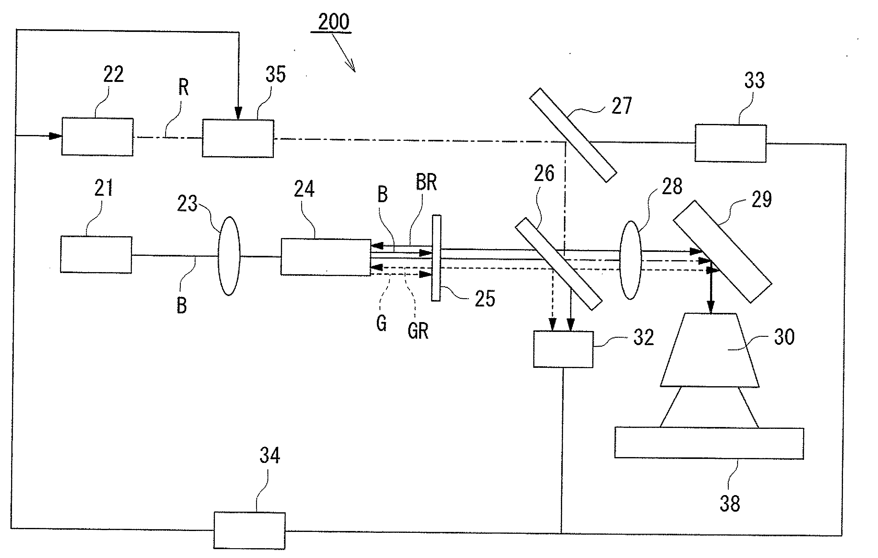
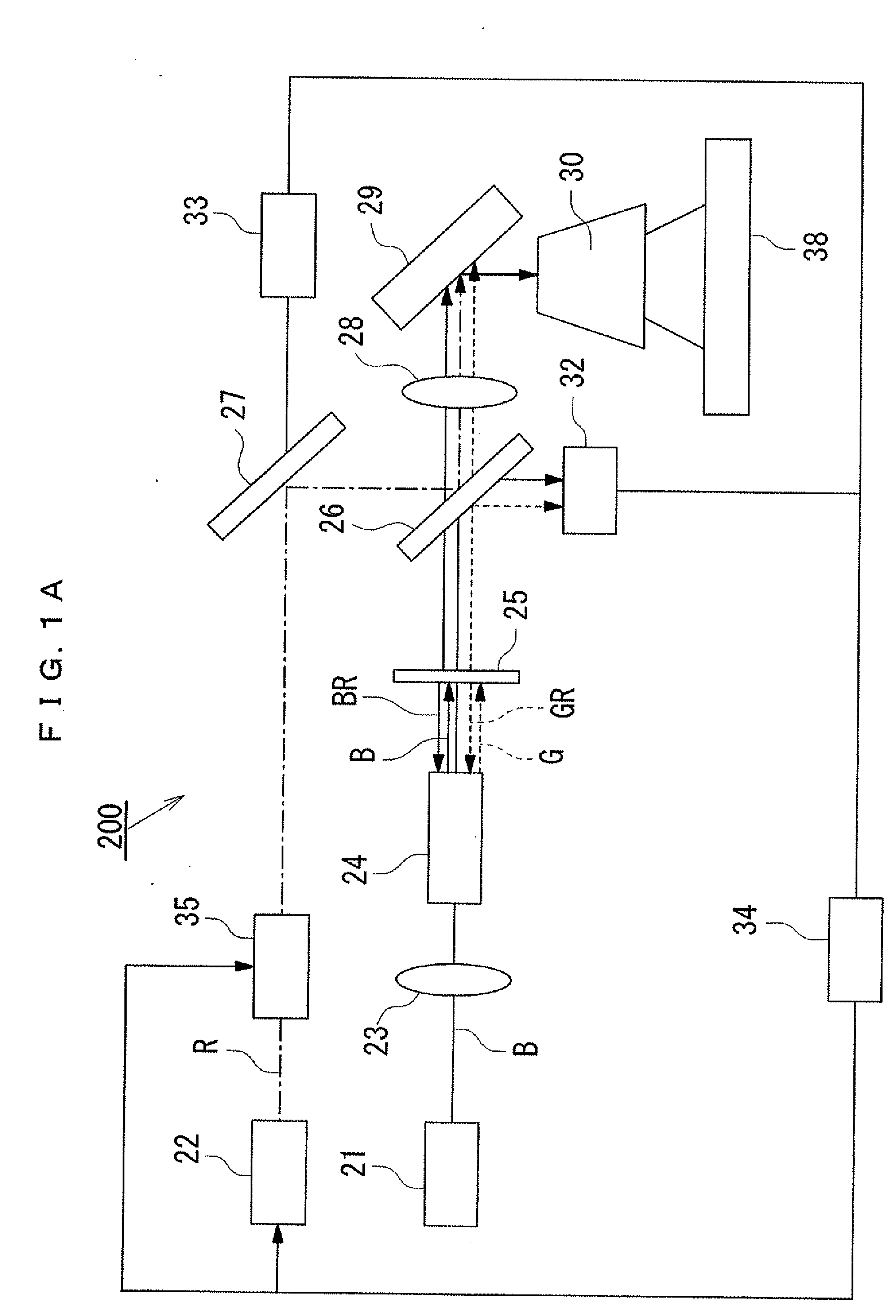
[0051]The first embodiment of the present invention will be hereinafter described with reference to the accompanying drawings. Based on FIGS. 1A and 2A, a projector according to the first embodiment of the present invention will be explained. Rotational control for a color wheel or light control after light passes through the color wheel may be any well-known art, so that the detail explanation thereof will be omitted.

[0052]According to a projector 200 as a projection image display device of a dual light-source type as shown in FIG. 1A, a blue illuminant 21 may be a laser light source, a light emitting diode, etc. Blue light emitted from the blue illuminant 21 is introduced into an integrator rod 24 after passing through a condensing lens 23. The integrator rod 24 may be a well-known device as long as light is allowed to be continuously reflected inside thereof. Light that has been passed through the integrator rod 24 will be then introduced into a color wheel 25...

second embodiment

The Second Embodiment

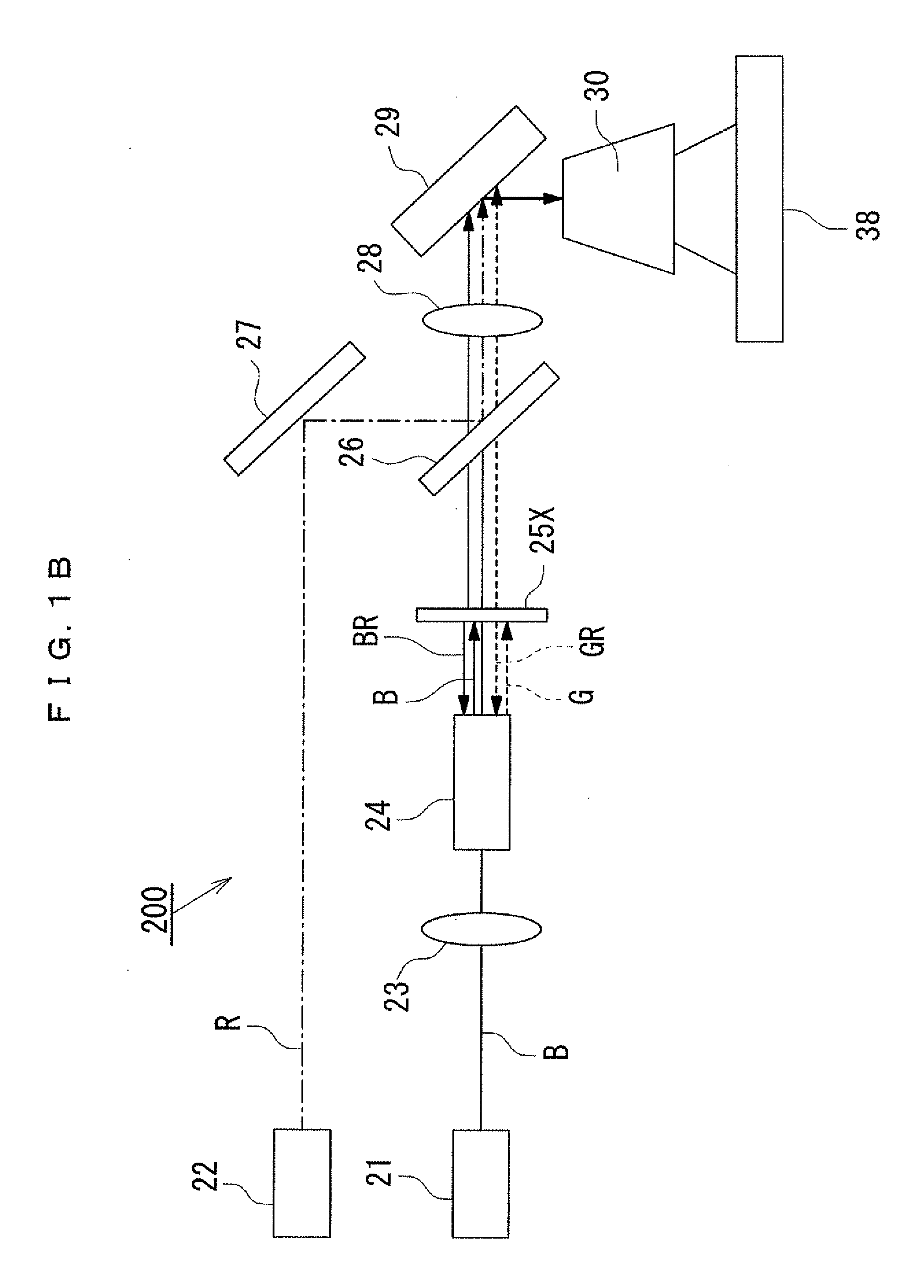
[0062]Next, compared to the projector 200 of the first embodiment, the second embodiment of the present invention will be hereinbelow explained with reference to FIG. 1B. The device of FIG. 1B does not include the light intensity detectors 32, 33, the light volume regulator 34, and the iris 35. The basic structure of a device shown in FIG. 1B is the same with the one of FIG. 1A. In a color wheel 25x, as shown in FIG. 2B, a green-light generating portion 352GP is formed, extended up to 240 degrees in the circumferential direction of a disc. The rest of the disc is formed with a blue-light generating portion 351GP. A green phosphor layer 352 may be formed at the most top layer of the green-light generating portion 352GP as shown in FIG. 3B(a). On the other hand, the blue-light generating portion 351GP includes an anti-reflection layer 350R (see FIG. 3B(b)). A region where the green phosphor layer 352 is formed is modifiable according to the ratio of transmitted li...

third embodiment

The Third Embodiment

[0066]Next, the third embodiment of a projection image display device of a single light-source type according to the present invention will be hereinbelow explained. In a projector 300 as shown in FIG. 9A, blue light emitted from a blue illuminant 41 passes through a lens 43 and then introduced into a color wheel 45 through an integrator rod 44. The color wheel 45 includes a color wheel main body 340 made of an optically permeable disc (see FIG. 11A) and, as shown in FIG. 10A, is divided into 4 sections in a circumferential direction. The 4 divided sections are composed of a green-light generating portion 342GP, a red-light generating portion 343GP, a blue-light generating portion 341GP that passes blue light, and a green-and-red light generating portion 344GP composed of mixed green and red phosphor layers.

[0067]As shown in FIGS. 11A(b) and 11A(c), between a green phosphor layer 342 and the color wheel main body 340, and also between a red phosphor layer 343 and...


PUM


Abstract

There is provided a projector at least comprising: a light source; a color wheel; a condensing lens; a spatial light modulator; and a projection optical system, wherein the light source includes a red illuminant and a blue illuminant, and the color wheel includes a disc made of optically permeable materials, the disc being composed of a green-light generating portion, a blue-light generating portion and a blue-and-green light generating portion, the green-light generating portion and the blue-and-green light generating portion each including a phosphor layer.

Description

BACKGROUND OF THE INVENTION[0001]1. Field of the Invention[0002]The present invention relates to a projector that magnifies and projects displayed images by means of a projection optical system so as to obtain large-screen displayed images. Especially, the present invention relates to a brightness-improved projector using a color wheel to which the filter element of a time-sharing type spectral device is applied.[0003]2. Description of the Related Art[0004]A projector (a projection-type image display device) used in home theaters, presentations, etc. in which to magnify and project displayed images by means of a projection optical system so as to obtain large-screen displayed images has been commercialized. This type of projector displays, while applying light sources as an illuminant, images on a screen through an electro-optical device using a spatial optical modulator such as a digital micromirror device or a liquid crystal display device. The projector may use a high-pressure me...

Claims


Application Information

Patent Timeline
Patent Type & Authority Applications(United States)
IPC IPC(8): G03B21/14
CPCG03B21/14H04N9/3161H04N9/3114G03B21/204G03B33/08
Inventor KATO, HIDEKIKITAMURA, ATSUSHI
Owner MINEBEA CO LTD
Why Eureka
Try Eureka