
High flux photon beams using optic devices

a technology of optic devices and photon beams, applied in the direction of nanoinformatics, nuclear engineering, therapy, etc., can solve the problems of poor signal-to-noise ratio, high false positives of edxrd, and inability to diffract strongly, etc., and achieve the effect of high-flux photon beams

Inactive Publication Date: 2011-08-25
GENERAL ELECTRIC CO
View PDF12 Cites 18 Cited by
  • Summary
  • Abstract
  • Description
  • Claims
  • Application Information

AI Technical Summary

Benefits of technology

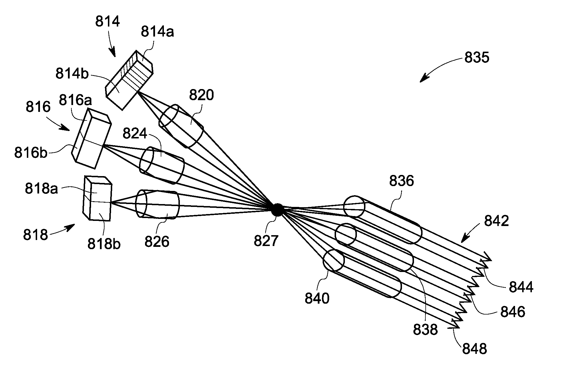
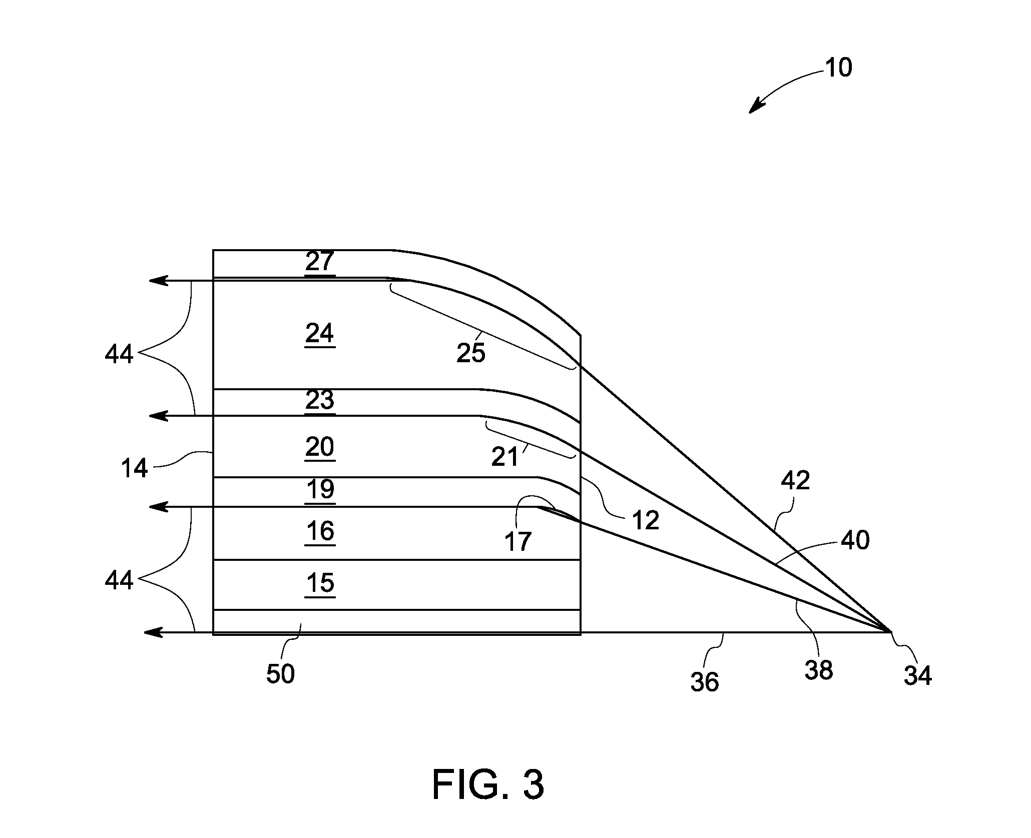
[0006]In one embodiment, a system for producing at least one high flux photon beam is provided. The system includes two or more photon sources configured to produce photon beams, and at least one first stage optic device coupled to at least one of the photon sources and providing at least one focused photon beam through total internal reflection, wherein at least one of the photon beams and the focused photon beams are combined at a virtual focal spot.
[0007]In another embodiment, a high flux photon beam system is provided. The system comprises two or more photon sources configured to produce photon beams, at least one first stage optic device coupled to at least one of the photon sources and providing at least one focused photon beam through total internal reflection, at least one virtual focal spot formed from the focused photon beam, and at least one second stage optic device coupled to the virtual focal spot and configured to generate a shaped photon beam.
[0008]In yet another embodiment, a system for producing high fl...

Problems solved by technology

Such EDXRD may suffer from high false positives due to poor signal-to-noise ratio in diffracted X-ray signals, which may stem from a variety of origins.
Third, some of the materials being searched for, e.g., explosives, may not diffract strongly, leading to diffuse peaks in measured X-ray spectra, as the materials are amorphous or polycrystalline.
Fourth, the diffracting volume may be small due to the need to improve the resolving capability of the system.
Most of these limitations arise from the type and configuration of threat materials being searched for in baggage and the nature of the X ray interaction with these materials, making all but the second limitation unavoidable.
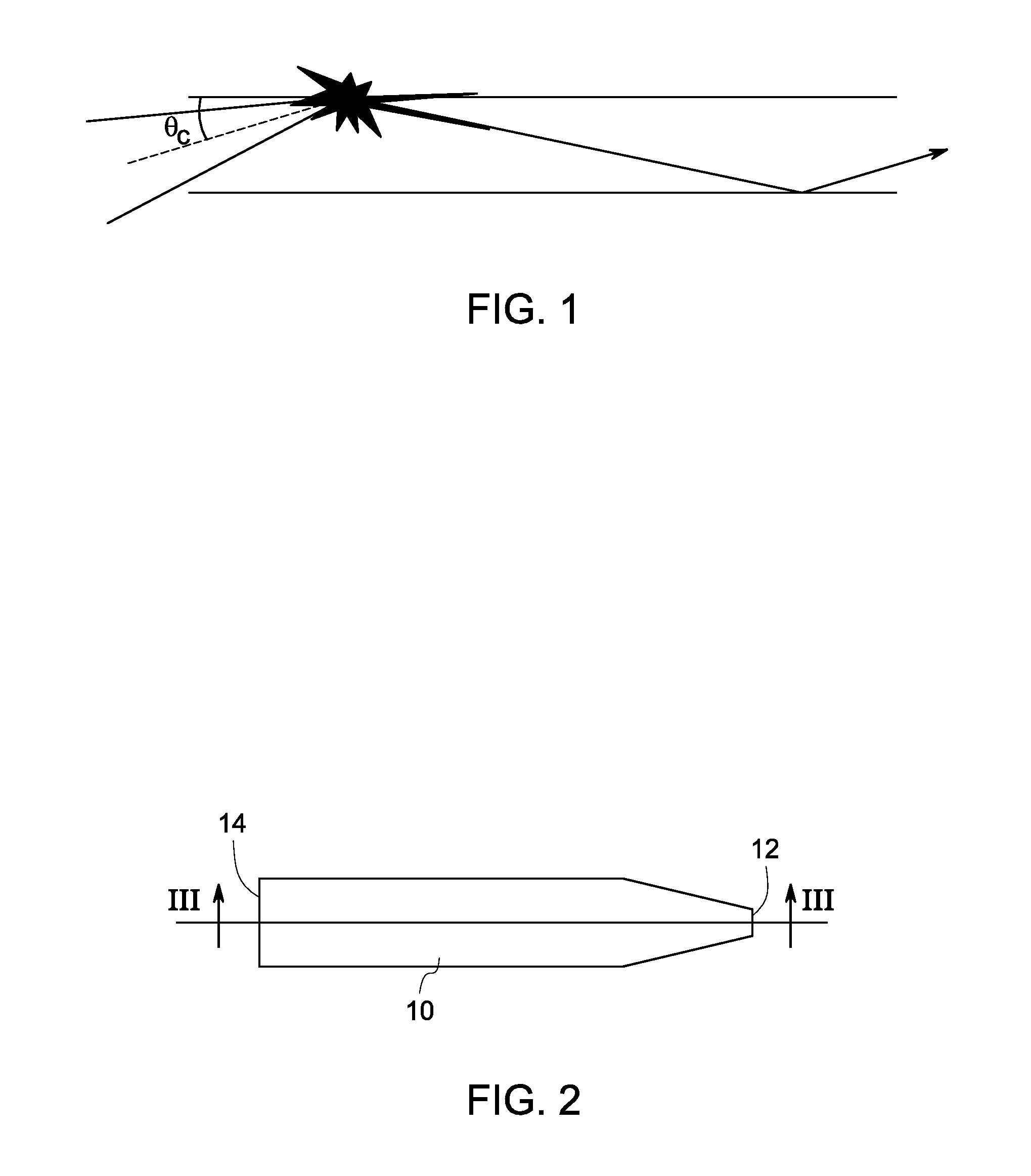
Total internal reflection from these types of optics typically becomes vanishingly small at energy levels above 60 keV, due to non-optimal differences in the real and imaginary parts of the refractive indices of air and glass.
In addition, the use of air as the high refractive index material in capillary or polycapillary optics prevents such optics from being placed within a vacuum, limiting their potential uses.

Method used


Image

  • High flux photon beams using optic devices
  • High flux photon beams using optic devices
  • High flux photon beams using optic devices

Examples


Embodiment Construction

[0018]The invention relates generally to re-direction of photon beams, and more particularly to systems and methods for producing high-flux photon beams. In certain embodiments, a system produces at least one high flux photon beam of higher flux than produced by existing laboratory-based X-ray sources. The system comprises two or more photon sources configured to produce photon beams. The system further comprises at least one first stage optic device coupled to at least one of the photon sources and providing at least one focused photon beam through total internal reflection, wherein at least one of the photon beams and the focused photon beam are combined at a virtual focal spot.

[0019]To more clearly and concisely describe the subject matter of the claimed invention, the following definitions are provided for specific terms, which are used in the following description and the appended claims. Throughout the specification, exemplification of specific terms should be considered as no...


PUM


Abstract

A system for producing at least one high flux photon beam is provided. The system includes two or more photon sources configured to produce photon beams, and at least one first stage optic device coupled to at least one of the photon sources and providing at least one focused photon beam through total internal reflection, wherein at least one of the photon beams and the focused photon beams are combined at a virtual focal spot.

Description

BACKGROUND[0001]The invention relates generally to re-direction of photon beams, and more particularly to systems and methods for producing high-flux photon beams[0002]Many imaging applications using photon radiation, such as X-ray radiation, require higher flux output to improve the signal-to-noise ratio in the measured data. Increasing X-ray flux may be accomplished, for example, by redirecting into usable directions X-ray radiation emitted by an X-ray source that would otherwise not contribute to the fidelity of the measured data. For example, energy-dispersive X-ray diffraction (EDXRD) may be used to inspect checked airline baggage for the detection of explosive threats or other contraband. Such EDXRD may suffer from high false positives due to poor signal-to-noise ratio in diffracted X-ray signals, which may stem from a variety of origins. First, the polychromatic X-ray spectrum used in EDXRD is produced by the Bremsstrahlung part of the source spectrum, which is inherently low...

Claims


Application Information

Patent Timeline
IPC IPC(8): H01J35/06G21K5/04H01J35/14
CPCB82Y10/00G21K1/062G21K1/067A61N5/1084G21K2201/064G21K2201/067G21K2201/061
Inventor LEE, SUSANNE MADELINEEDIC, PETER MICHAELMANI, VANITAHOPKINS, FORREST FRANKNEUSER, EBERHARD
Owner GENERAL ELECTRIC CO
Learn More