Method and System for Providing Air to an Engine

a technology for providing air to engines and air intakes, applied in mechanical equipment, machines/engines, electric control, etc., can solve the problems of reducing the amount of work used to pressurize engine air, affecting the efficiency of engines, so as to reduce engine pumping losses, reduce engine displacement, and increase engine efficiency

Active Publication Date: 2011-09-01
FORD GLOBAL TECH LLC
View PDF17 Cites 17 Cited by
  • Summary
  • Abstract
  • Description
  • Claims
  • Application Information

AI Technical Summary

Benefits of technology

Engine efficiency can be increased while providing a desired engine output capacity by lowering engine displacement and compressing air supplied to the engine. Lowering the engine displacement can reduce engine pumping losses and pressurizing engine intake air can increase output power of a smaller displacement engine. Consequently, a smaller displacement engine can provide improved fuel economy as compared

Problems solved by technology

However, compressors can experience surge when flow through the compressor is low and when the pressure differential across the compressor is relatively high.
Surge may be undesirable for s

Method used


Image

  • Method and System for Providing Air to an Engine
  • Method and System for Providing Air to an Engine
  • Method and System for Providing Air to an Engine

Examples


Embodiment Construction

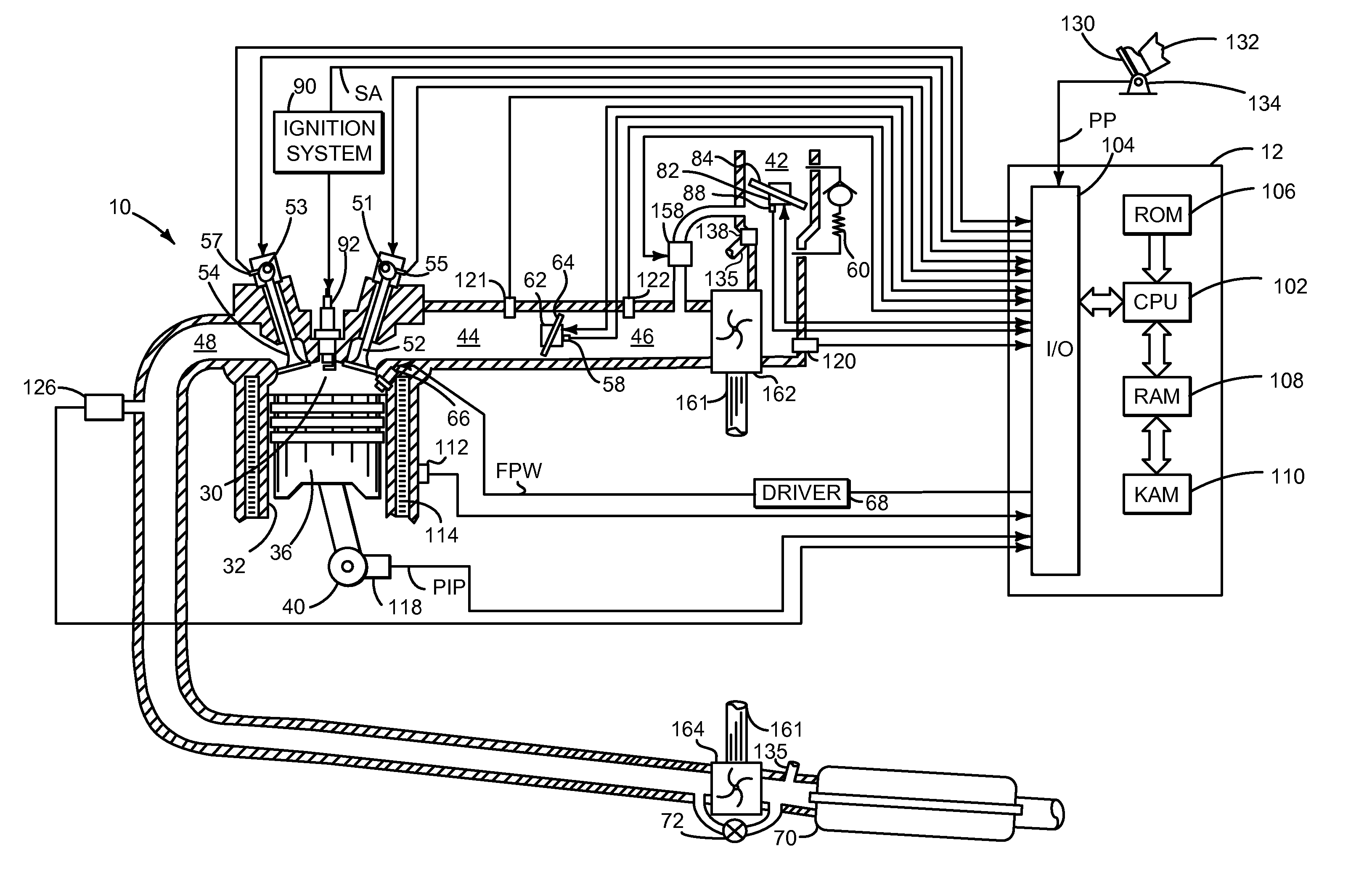
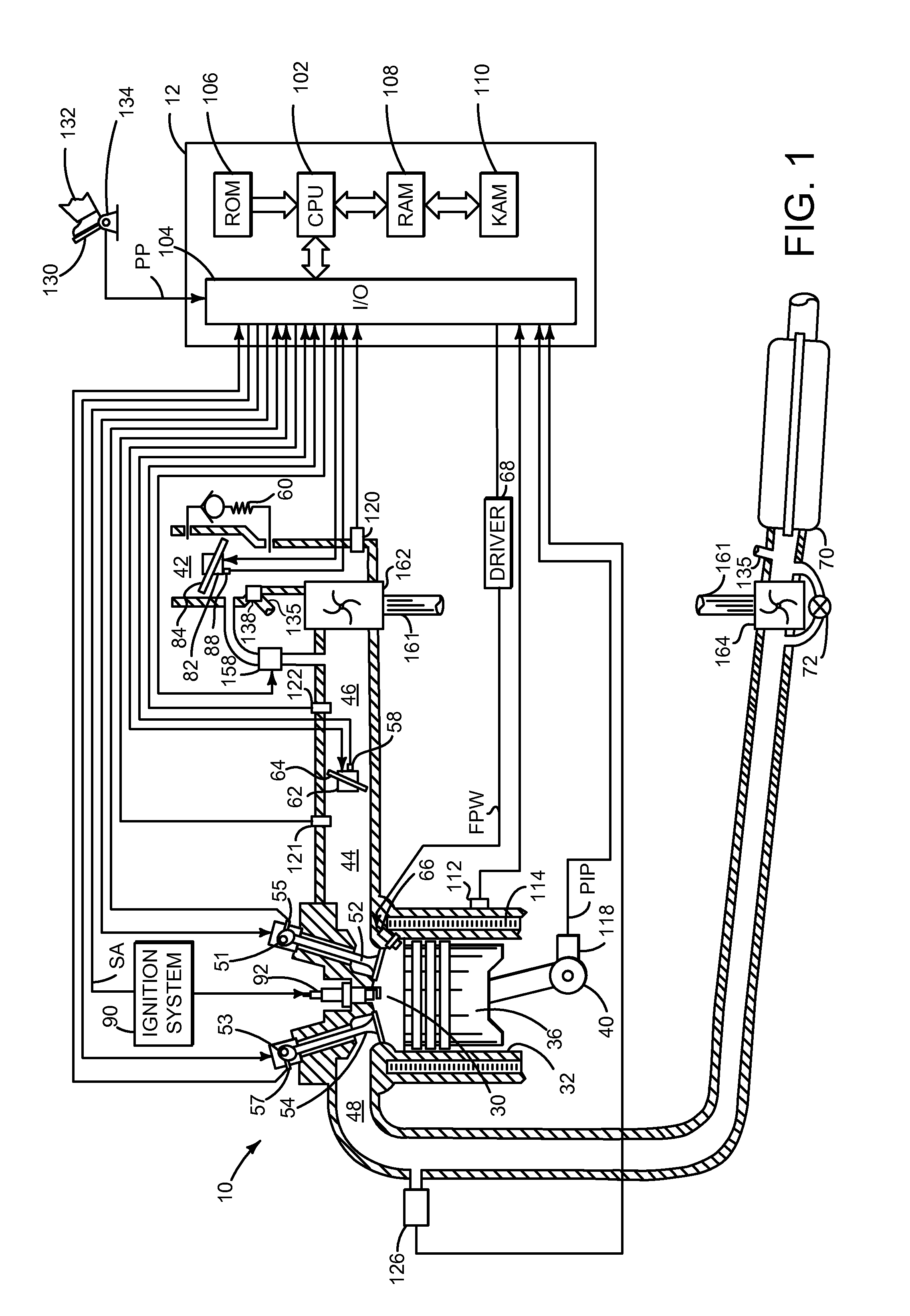
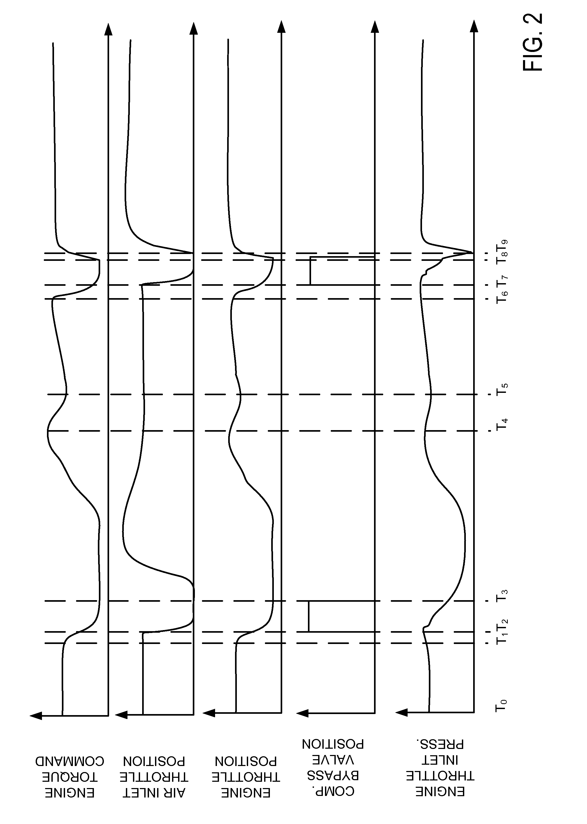
The present description is related to providing air to an engine. In particular, the present description provides an approach for reducing the possibility of producing noise during conditions of low flow and a higher pressure ratio across a compressor. FIG. 1 shows an example system for providing air to an engine. FIGS. 2 through 5 show simulated signals of interest when providing air to an engine. FIG. 6 shows a method for providing air to an engine and the control illustrated in FIGS. 2-5.

Referring to FIG. 1, internal combustion engine 10, comprising a plurality of cylinders, one cylinder of which is shown in FIG. 1, is controlled by electronic engine controller 12. Engine 10 includes combustion chamber 30 and cylinder walls 32 with piston 36 positioned therein and connected to crankshaft 40. Combustion chamber 30 is shown communicating with intake manifold 44 and exhaust manifold 48 via respective intake valve 52 and exhaust valve 54. Each intake and exhaust valve may be operated...


PUM


Abstract

Systems and methods for supplying air to an engine are disclosed. In one example, an air inlet throttle is at least partially closed in response to a change in engine torque request. In another example, the air inlet throttle is adjusted in conjunction with adjusting an engine throttle. The approach can reduce compressor noise and may reduce the possibility of compressor surge.

Description

BACKGROUND / SUMMARYEngine efficiency can be increased while providing a desired engine output capacity by lowering engine displacement and compressing air supplied to the engine. Lowering the engine displacement can reduce engine pumping losses and pressurizing engine intake air can increase output power of a smaller displacement engine. Consequently, a smaller displacement engine can provide improved fuel economy as compared to a larger displacement engine while providing an amount of power that is similar to the larger displacement engine. However, compressors can experience surge when flow through the compressor is low and when the pressure differential across the compressor is relatively high. Surge may be undesirable for several reasons including because surge may induce undesirable noise from the engine air intake system.The inventors herein have recognized the above-mentioned disadvantages and have developed a method for supplying air to an engine, comprising: controlling air ...

Claims


Application Information

Patent Timeline
IPC IPC(8): F02B39/16
CPCF02B37/16F02B37/18F02D41/0007F02D41/005Y02T10/144F02D2041/0017F02D2250/18F02M25/0709F02D41/1497F02M26/06Y02T10/12F02D41/0005Y02T10/40
Inventor ULREY, JOSEPH NORMANDOERING, JEFFREY ALLENPURSIFULL, ROSS DYKSTRALEWIS, DONALD J.
Owner FORD GLOBAL TECH LLC
Why Eureka
Try Eureka