Hot-cold inlet pipe structure

a technology of hot-cold water inlet pipe and pipe structure, which is applied in the direction of fluid cut-off means, mechanical devices, engine components, etc., can solve the problems of increasing manufacturing costs, labor intensive work, time-consuming, etc., and achieve the effect of reducing the cost of metallic materials in the raw material

Inactive Publication Date: 2011-09-01
CHUNG CHENG FAUCET
View PDF30 Cites 11 Cited by
  • Summary
  • Abstract
  • Description
  • Claims
  • Application Information

AI Technical Summary

Benefits of technology

[0006]Aspects of the invention overcome shortcomings of prior technologies by introducing an external-threaded pipe with an internal pipe forming an integrated design of a hot-cold wa

Problems solved by technology

This is a labor intensive work and is time consuming.
As such, metallic

Method used


Image

  • Hot-cold inlet pipe structure
  • Hot-cold inlet pipe structure
  • Hot-cold inlet pipe structure

Examples


Embodiment Construction

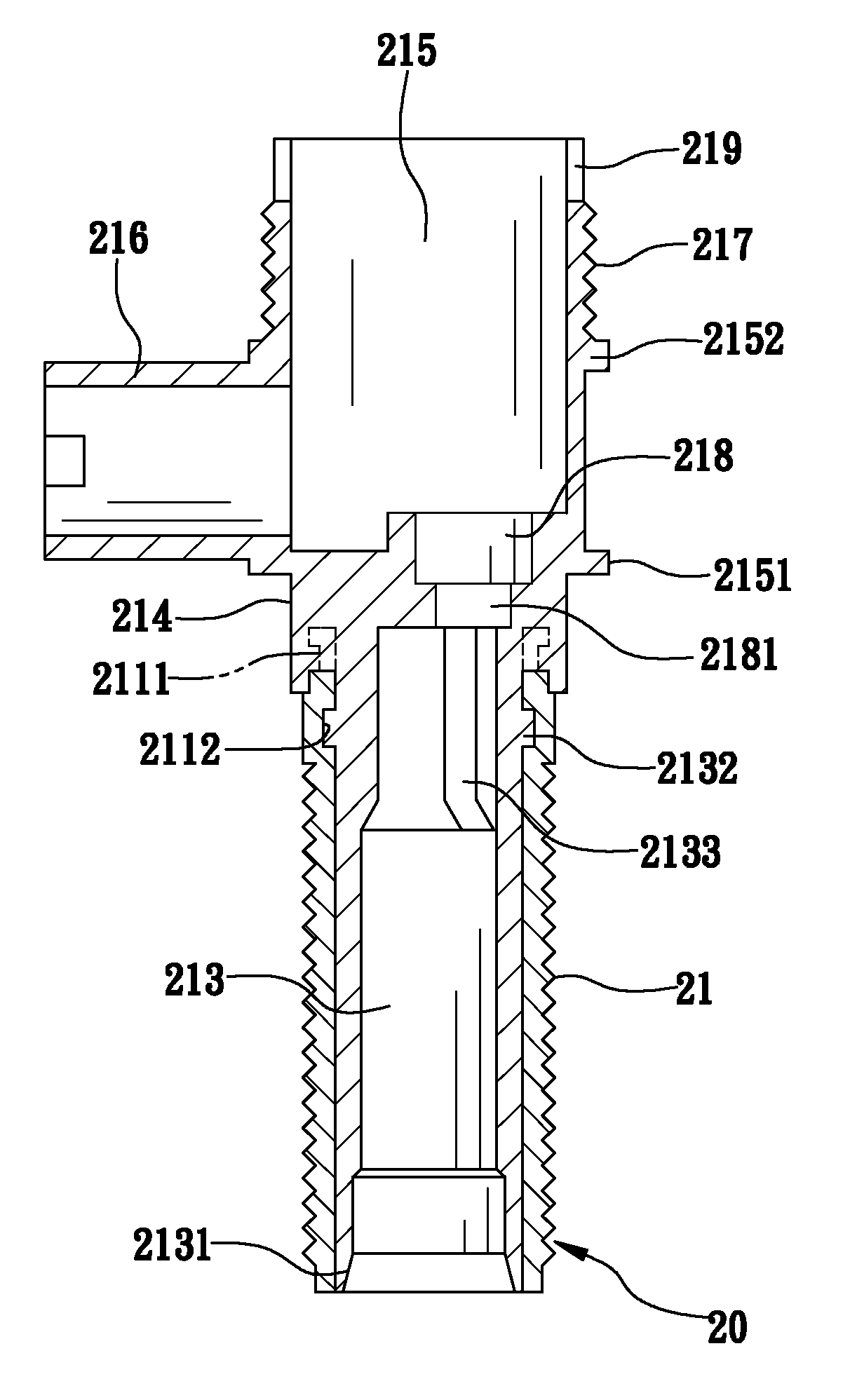
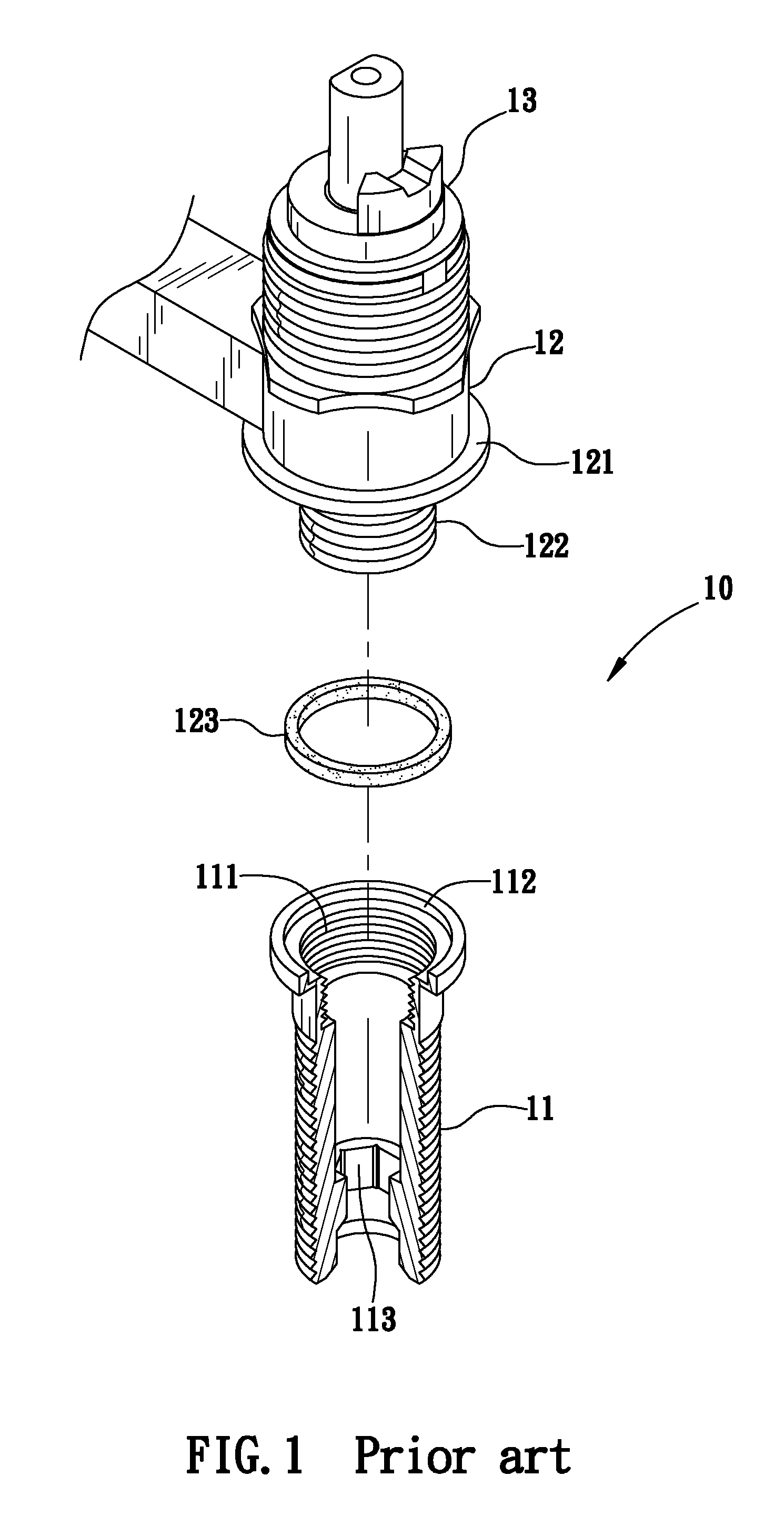
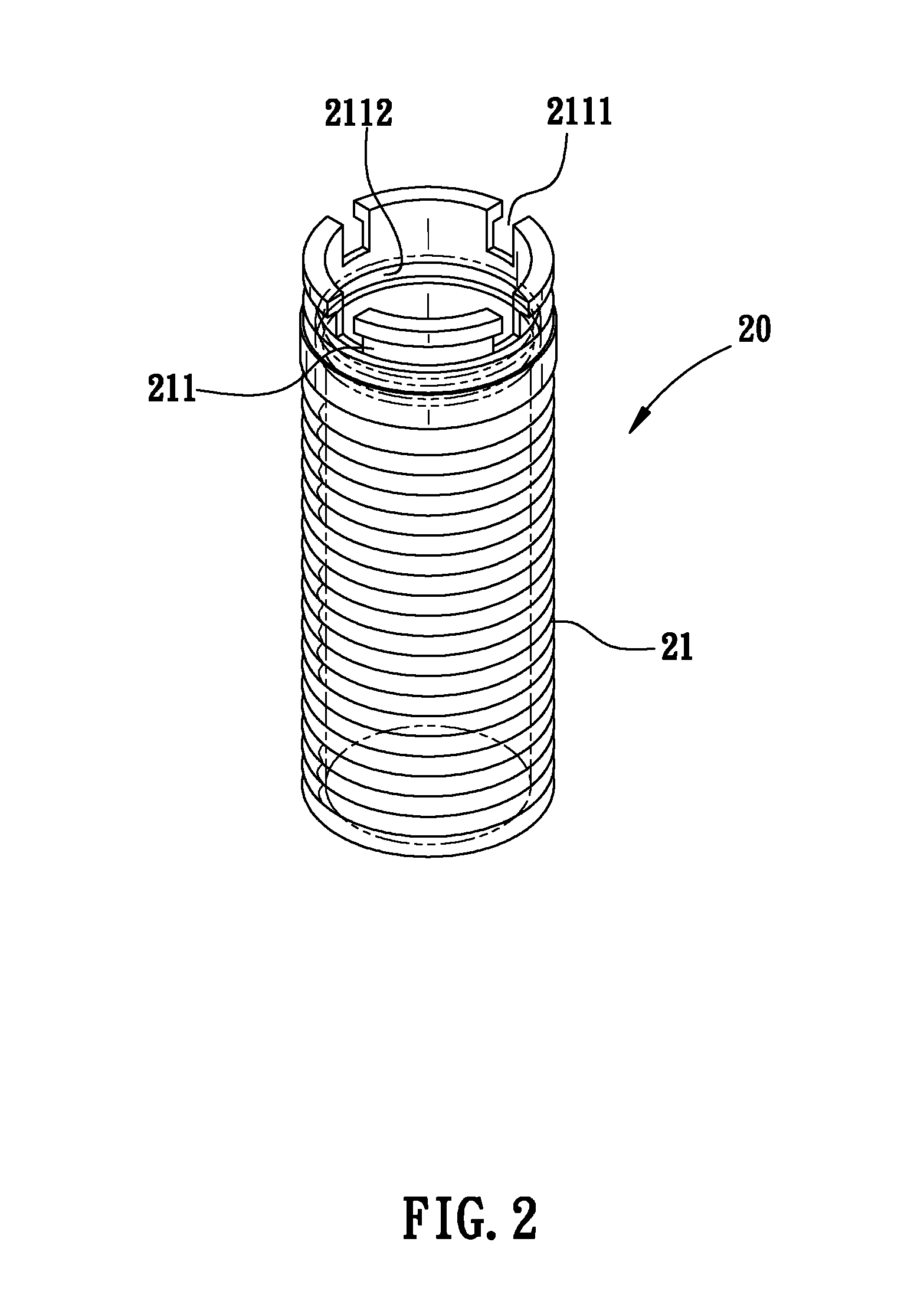
[0036]The following list shows reference characters used through FIGS. 1-24:[0037]20 and 20′—an inlet pipe;[0038]21—an external-threaded pipe;[0039]211—a locking ring;[0040]2111 and 2111′—a slit;[0041]2112—a ring groove;[0042]212—an inner wall;[0043]213 and 213′—an internal pipe;[0044]2131 and 2131′—a corner;[0045]2132 and 2132′—a protruding ring;[0046]2133 and 2133′—a strengthen band;[0047]214 and 214′—a connecting section;[0048]215—a receiving chamber;[0049]2151—a first stopping ring;[0050]2152—a second stopping ring;[0051]215′—a cap;[0052]215″—a water-receiving area;[0053]2151′—a stopping ring;[0054]2152′—a connecting base;[0055]2153′—a first limiting slit;[0056]216 and 216′—a pipe section;[0057]2161—a second limiting slit;[0058]2161′—a first strengthening rib;[0059]2162—a second strengthening rib;[0060]217—an external thread section;[0061]218—a water-entry ring base;[0062]2181—a stopping ring;[0063]219—a locking slit;[0064]30 and 30′—a control valve;[0065]31′—a rotating axle;[00...


PUM


Abstract

An improved hot-cold inlet pipe structure includes an external-threaded pipe and an internal pipe forming an integrated piping structure. The internal pipe extends outwardly a wrapping section that covers a plurality of threaded openings of the external pipe. The internal pipe is composed of non-toxic materials that include plastic materials that are high resistance to pressure and climate change. The internal pipe also reduces the use of metallic materials and does not release of toxic chemical to water stream. A depressed section of the interior of a top of end of the inlet pipe includes a receiving chamber, the receiving chamber includes an opening that includes numerous slots. The slots receive a control valve unit such that the slots mesh with the control valve unit. This design is also beneficial in the manufacturing of the inlet pipe.

Description

BACKGROUND OF THE INVENTION[0001]1. Field of the Invention[0002]Embodiments of the invention generally relate to an improvement on hot-cold water inlet pipe structure. This design uses an external-threaded pipe and an inner pipe to form an integrated inlet pipe. This design further improves strength of raw materials, as well as lowers usage of metallic raw materials. The inner pipe also includes a receiving groove and a corresponding inlet ring to prevent leakage. At the same time, aspects of the invention decrease the complicated process of assembly, which also improve the application of the invention.[0003]2. Background of the Invention[0004]According to previous technology, such as a hot-cold water inlet pipe 10 shown in FIG. 1, the pipe 10 includes a metallic inlet pipe 11 with a control valve 13 and a valve base 12. The inlet pipe 11 includes an internally threaded section 111 on one side. At a distal end of the threaded section 111, a stopping end 112 is threaded. Also, the va...

Claims


Application Information

Patent Timeline
IPC IPC(8): F16L9/14
CPCE03C1/0403E03C1/0401
Inventor KO, HSI CHIAKO, JUI FENG
Owner CHUNG CHENG FAUCET
Why Eureka
Try Eureka