Omni-directional vehicle

a technology of omni-directional vehicles and motor vehicles, applied in the field of vehicles, can solve the problems of imposing some limit as to the useful applications of vehicles, inability to sharpen turns, and large lateral dimensions of vehicles, and achieves the effects of reducing the number of components, simplifying the overall structure, and facilitating maneuvering

Active Publication Date: 2011-09-01
HONDA MOTOR CO LTD
View PDF26 Cites 71 Cited by
  • Summary
  • Abstract
  • Description
  • Claims
  • Application Information

AI Technical Summary

Benefits of technology

[0011]According to such a structure of the present invention, the ground contact member contributes to the maintenance of an upright orientation of the vehicle. Furthermore, when the ground contact member consists of a non-rotatable member or a secondary wheel which is enabled to restrict the direction of the movement of the vehicle, it is possible to turn the vehicle body by causing the driven road wheel to turn around the center of the circular cross section thereof, causing the vehicle body to move sideways, while the ground contact member is brought into contact with the ground. Therefore, the vehicle is enabled not only to move horizontally in the fore-and-aft direction but to make a turn. In particular, the vehicle is enabled to make a turn of a desired turning radius which is determined by the distance between the ground contact point of the driven road wheel and ground contact point of the ground contact member. Thus, the vehicle can make a sharp turn without causing any significant change to the posture of the rider, and can favorably maneuver in narrow places in a convenient manner.
[0012]According to a preferred embodiment of the present invention, the drive assembly comprises a pair of rotary members disposed on the vehicle body one next to the other in a mutually axially spaced relationship and rotatable around a common central axial line (A), a pair of drive units for individually actuating the rotary members, respectively, a plurality of free roller provided along a circumference of each rotary member, wherein the driven road wheel is axially interposed between and supported by the free rollers of the two rotary members so as to be rotatable around a same central axial line (B) as the central axial line (A) of the rotary members, and each free roller is supported so as to be rotatable around a central axial line or rotation axis (D) related to the central axial line (B) of the driven road wheel as skew lines and engage an outer surface of the driven road wheel.
[0013]According to this embodiment, the driven road wheel is interposed between the rotary members via the free rollers so that the rolling contact between the driven road wheel and free rollers is ensured, and the overall structure is simplified.
[0014]According to another embodiment of the present invention, the drive assembly comprises a rotary member disposed so as to be rotatable around the same central axial line (A) as the annular member, a drive unit for rotatively actuating the rotary member, and a plurality of free rollers mounted on a periphery of the rotary member, wherein the driven road wheel is disposed opposite to the rotary member and engaged by the free rollers of the rotary member axially from one side thereof, and each free roller is supported so as to be rotatable around a rotation axis (D) related to the central axial line (B) of the driven road wheel as skew lines and engage an outer surface of the driven road wheel.
[0015]According to this embodiment, the drive assembly is required to have only one rotary member, and the number of component parts is reduced.
[0016]According to yet another embodiment of the present invention, the ground contact member comprises a pair of secondary wheels which are configured to engage points of a ground surface laterally spaced from the driven road wheel and are provided with a central axial line extending in parallel to that of the driven road wheel, each secondary wheel being provided with an individually operable braking unit. Braking one of the secondary wheels causes a yaw moment to be applied to the vehicle, and allows the vehicle to make a turn in a desired direction. If the ground contact member consists of a secondary wheel that can be actuated sideways and roll freely in a fore-and-aft direction, the vehicle can not only travel freely in the fore-and-aft direction but also to freely make a turn without regard to if the vehicle is traveling or stationary. Therefore, the vehicle is enabled to make highly sharp turns. If an arm supporting the secondary wheel is configured to be resiliently tilted so that the braking force may be adjusted in dependence on the tiling angle of the arm, a highly maneuverable omni-directional vehicle can be provided.

Problems solved by technology

Therefore, a certain turning radius is required when making a turn, and a sharp turn is not possible.
This may impose some limit as to the useful applications of the vehicle.
Also, because of the need to tilt the axle, the surface supporting the rider inevitably tilts when making a turn, and this necessitates the rider to adjust his or her posture to the tilting of the supporting surface.
However, because the two wheels are required to be placed in parallel to each other, the lateral dimension of the vehicle is so large that the vehicle may not be useable in narrow places.

Method used


Image

  • Omni-directional vehicle
  • Omni-directional vehicle
  • Omni-directional vehicle

Examples


Embodiment Construction

)

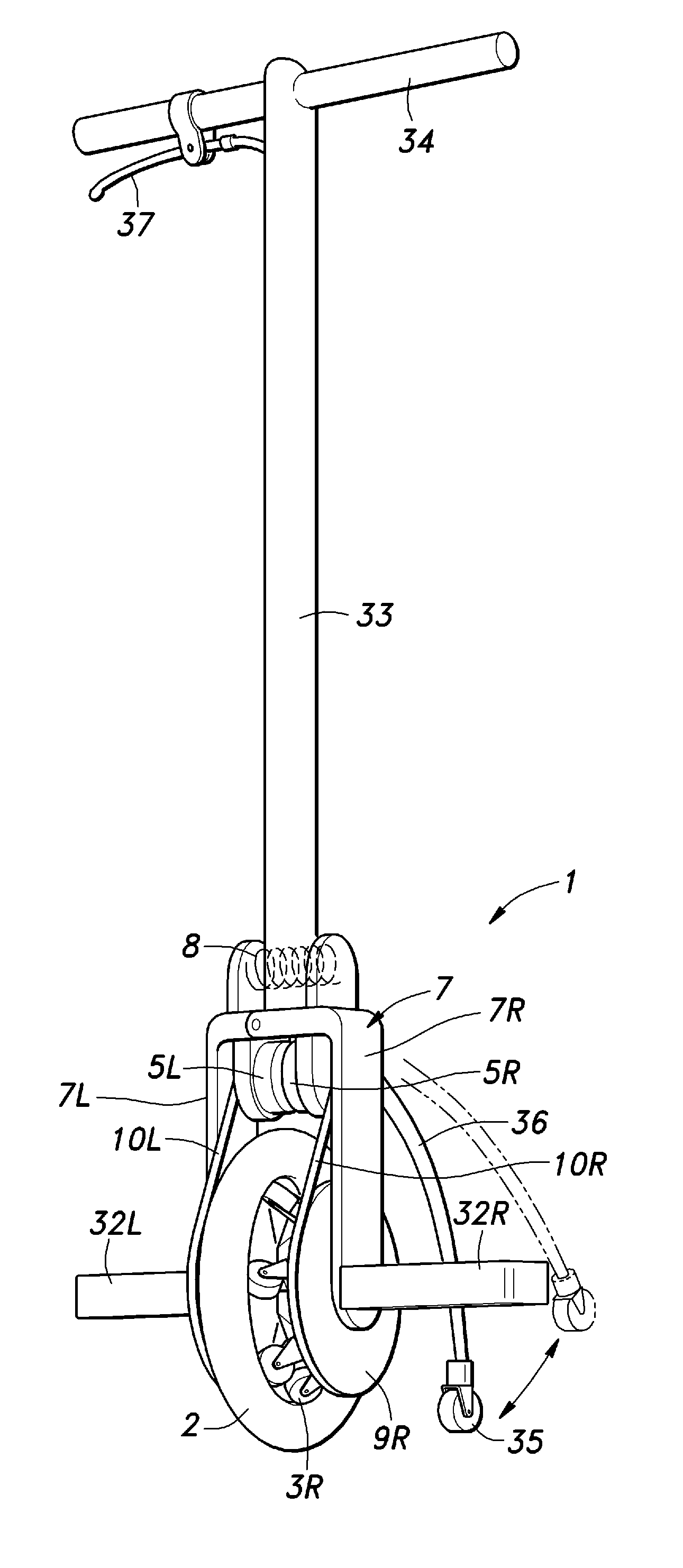
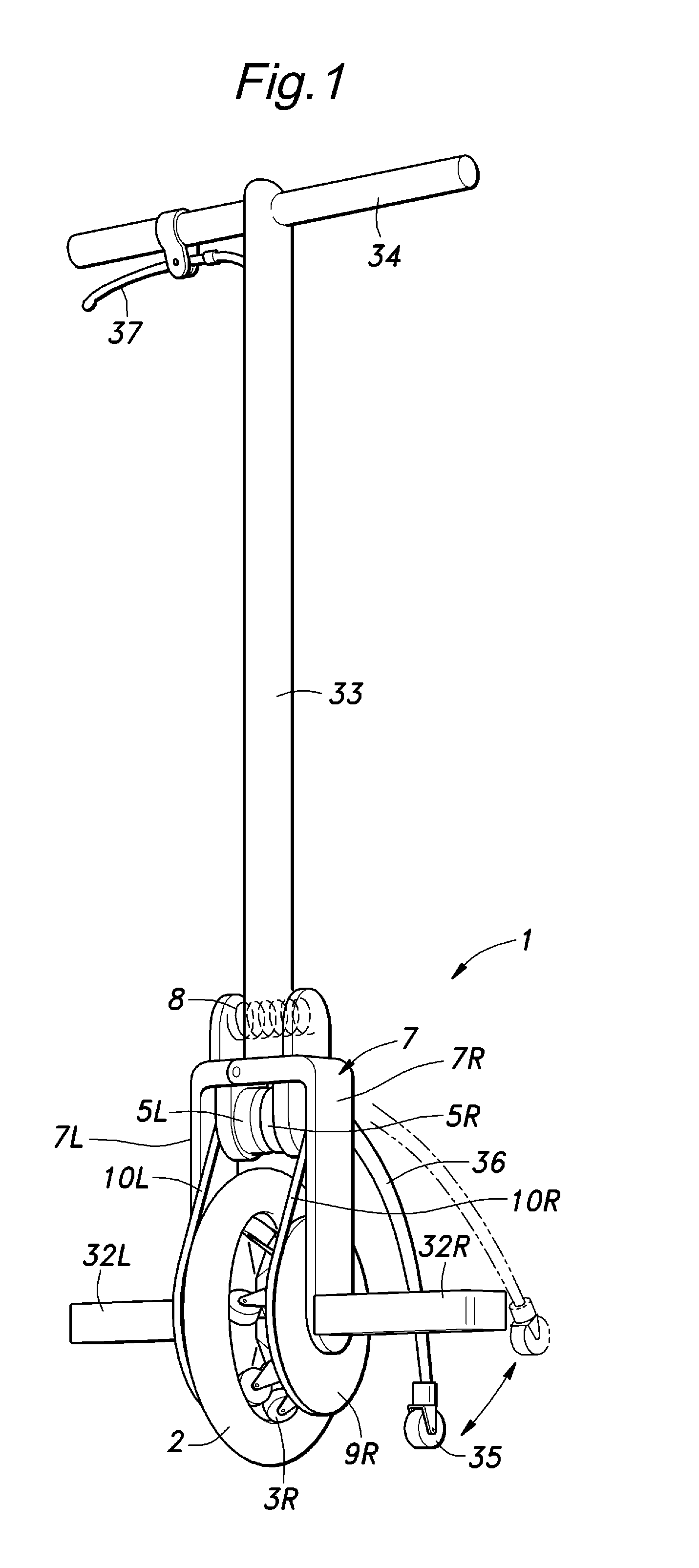
[0017]A preferred embodiment of the vehicle of the present invention is described in the following with reference to FIGS. 1 to 7.

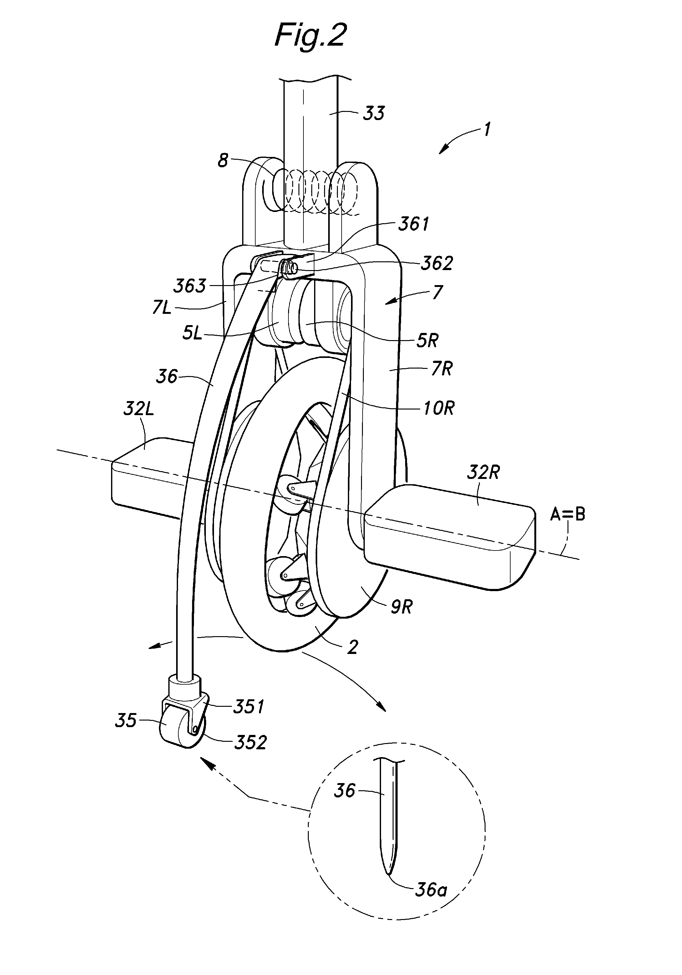
[0018]The vehicle of the illustrated embodiment is provided with a yoke-shaped vehicle body 7 and a driven road wheel 2 supported by the vehicle body 7.

[0019]The vehicle body 7 comprises a right leg member 7R and a left leg member 7L connected to the right leg member 7R via a hinge having a hinge pin 71. The right leg member 7R is fitted with a horizontally extending right step 32R, and the left leg member 7L is fitted with a horizontally extending left step 32L. To the right leg member 7R is fixedly connected a lower end of a pole 33. The pole 33 extends vertically from the vehicle body 7, and is provided with a horizontal handle bar 34 at an upper end thereof. The vehicle body 7 of the vehicle 1 is thus an integral assembly of the right and left steps 32R and 32L, pole 33 and handle bar 34.

[0020]To the vehicle body 7 is attached a secondary wheel 35 vi...


PUM

PropertyMeasurementUnit
tilting angleaaaaaaaaaa
flexibleaaaaaaaaaa
angleaaaaaaaaaa

Abstract

[Task] Provided is a vehicle that can make tight turns without significantly changing an attitude of a rider, and is highly convenient in narrow places.
[Solution] A omni-directional one-wheeled vehicle comprises a vehicle body (7) and a secondary wheel (35) configured to contact a ground surface at a point displaced from a contact point of a driven road wheel (2).

Description

TECHNICAL FIELD[0001]The present invention relates to a vehicle on which a person can ride, and in particular to a one-wheeled omni-directional motor vehicle.BACKGROUND OF THE INVENTION[0002]A vehicle including a chassis for supporting a rider and a wheel provided centrally on the chassis is known (See Patent Document 1). Also is known a vehicle including a pair of wheels disposed one next to the other and a step platform provided between the two wheels or on either outer side of the two wheels (See Patent Document 2) for placing the feet of a rider thereon.Patent Document 1:[0003]Japanese patent laid open publication No. 2004-129435 (FIGS. 39 to 42) Patent Document 2:[0004]Japanese patent laid open publication No. 2006-008013 (FIGS. 31 to 34)BRIEF SUMMARY OF THE INVENTIONTask to be Achieved by the Invention[0005]The vehicle disclosed in Patent Document 1 is enabled to make a turn by tilting an axle of the wheel, and thereby changing the effective radius of the contact surface of a ...

Claims


Application Information

Patent Timeline
Patent Type & Authority Applications(United States)
IPC IPC(8): B62D9/00B62D61/00B62D51/02
CPCB60B19/003B60B19/125B60B2360/10B62K3/007B60B2360/50B62H1/12B62K1/00B60B2360/32B62K11/007
Inventor TAKENAKA, TORUHIRANO, MAKOTOIZUMI, HIDEHARUKUWABARA, KAZUYAKOYAMA, TAIJIKOBASHI, SHINICHIRO
Owner HONDA MOTOR CO LTD
Why Eureka
Try Eureka