Non-contact type power receiving apparatus, electronic equipment and charging system using the power receiving apparatus

a power receiving apparatus and non-contact technology, applied in the direction of safety/protection circuits, inductances, transportation and packaging, etc., to achieve the effect of effective control of oscillation

Active Publication Date: 2011-09-01
KK TOSHIBA +1
View PDF9 Cites 91 Cited by
  • Summary
  • Abstract
  • Description
  • Claims
  • Application Information

AI Technical Summary

Benefits of technology

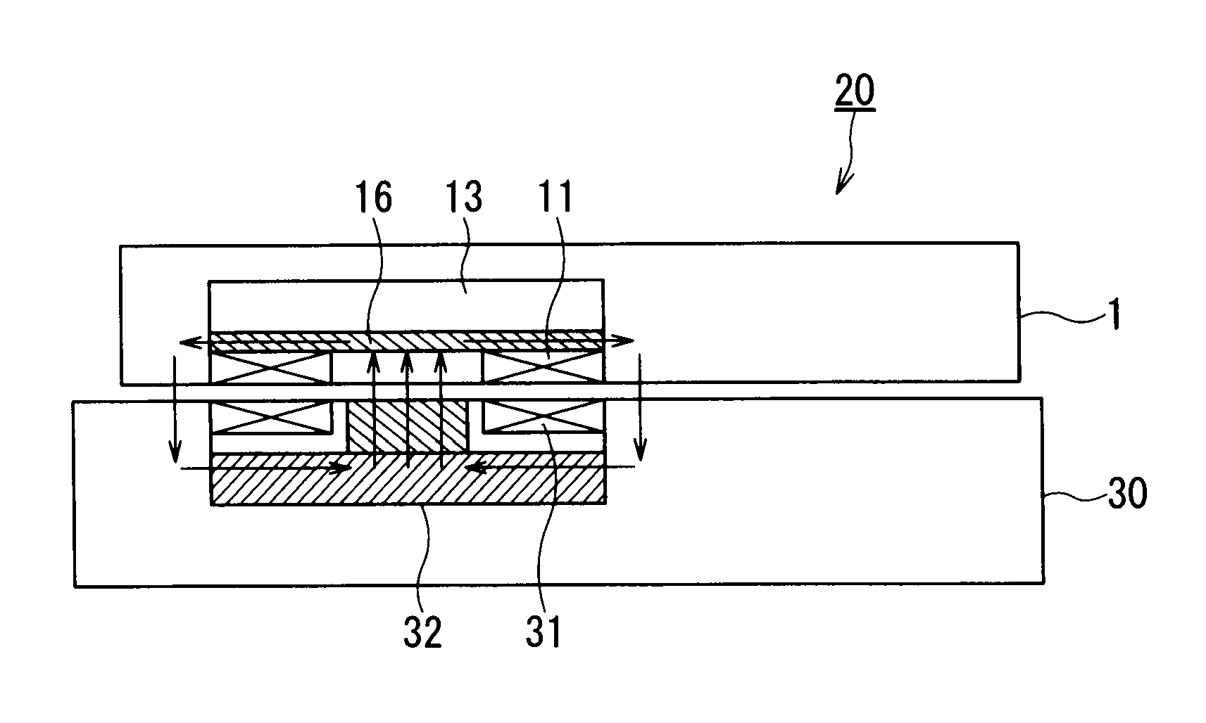
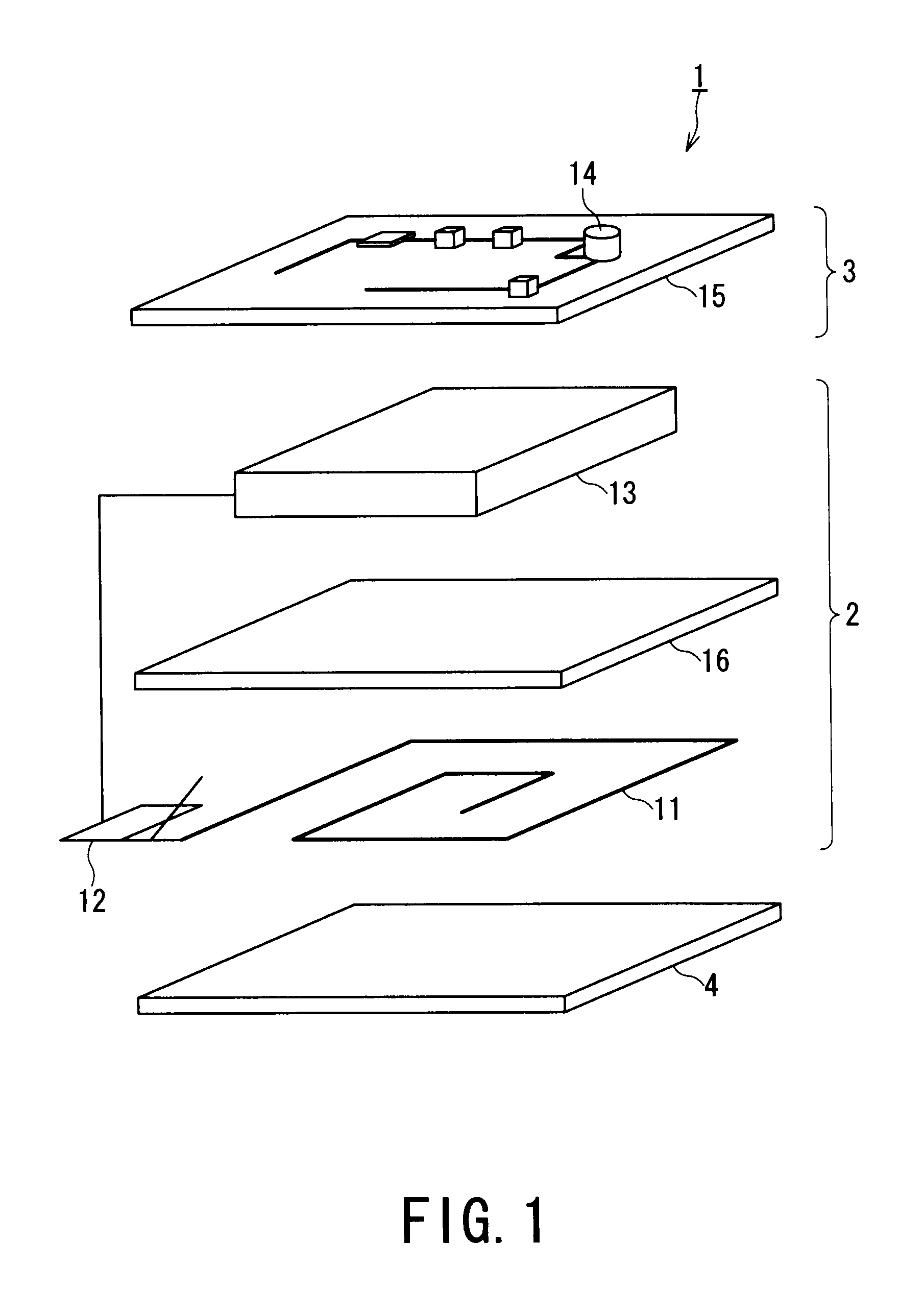
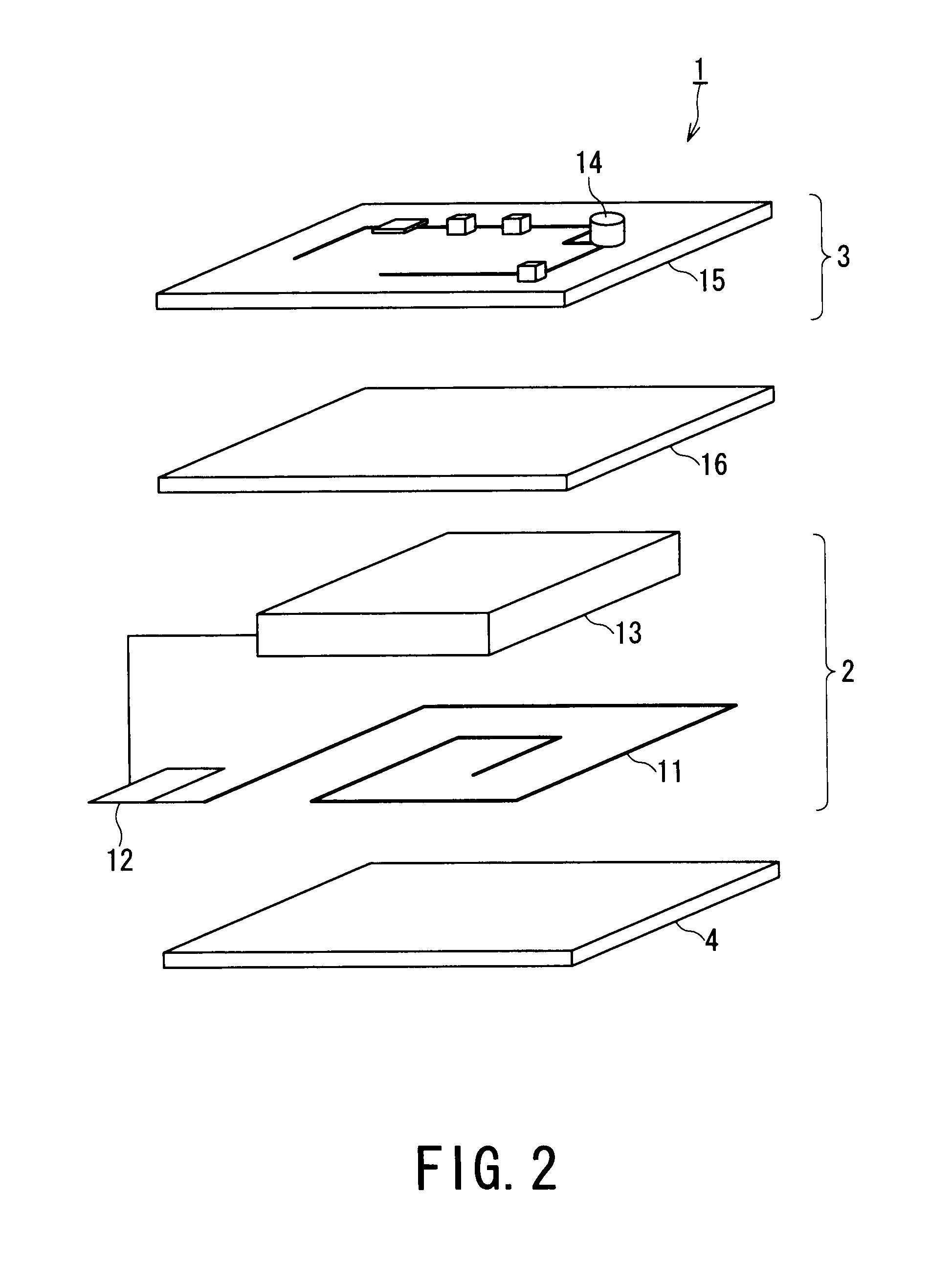
[0027]According to the present invention, the composite magnetic body comprising a plurality of magnetic sheets (magnetic ribbons) is provided to at least one portion between the spiral coil (power receiving side spiral coil: a secondary coil) and the secondary battery, and a portion between the rectifier and the spiral coil. Therefore, magnetic flux generated from a power charging side spiral coil (a primary coil) is prevented from interlinking with a circuit board and the secondary battery or the like, and inductance variation in the preliminary coil, which is caused by absence or presence of the secondary coil, is controlled while noise and heat generation originated by induced electromotive force (electromagnetic induction) are suppressed, so that a resonating property of a resonance circuit constituted by the primary coil is improved whereby an oscillation can be effectively controlled.

Problems solved by technology

According to the above conventional arrangement, there has been posed problems such that a fluctuation in inductance of the primary coil becomes notable, and an operating condition of the resonance circuit is disadvantageously deviated from resonance condition capable of exhibiting a sufficient effect in accordance with the positional relationship between the magnetic body and the primary coil.

Method used


Image

  • Non-contact type power receiving apparatus, electronic equipment and charging system using the power receiving apparatus
  • Non-contact type power receiving apparatus, electronic equipment and charging system using the power receiving apparatus
  • Non-contact type power receiving apparatus, electronic equipment and charging system using the power receiving apparatus

Examples


example 1

[0076]A composite magnetic body adjacent to the secondary coil was prepared in the following manner. Namely, there was prepared a Co-type amorphous sheet (ribbon) having a composition of Co70 Fe5 Si5 B20 (atomic ratio), a saturation magnetic flux density Ms of 0.55, and an average thickness (t) of 20 μm. Then, the Co-type amorphous sheet was subjected to a heat treatment at 200° C. for 30 minutes. The heat-treated sheet was worked to provide a size of 35 mm×35 mm. A polycarbonate resin having a thickness of 25 μm was attached to both surfaces of the worked sheet through an adhesive layer having a thickness of 10 μm thereby to prepare a first magnetic sheet.

[0077]On the other hand, there was prepared a Co-type amorphous sheet (ribbon) having a composition of CO70 Fe5 Si5 B20 (atomic ratio), a saturation magnetic flux density Ms of 0.55, and an average thickness (t) of 20 μm. Then, the Co-type amorphous sheet was subjected to a heat treatment at 350° C. for 60 minutes. The heat-treate...

example 2

[0078]A composite magnetic body adjacent to the secondary coil was prepared in the following manner. Namely, there was prepared a Co-type amorphous sheet (ribbon) having a composition of CO70 Fe5 Si5 B20 (atomic ratio), a saturation magnetic flux density Ms of 0.55, and an average thickness (t) of 20 μm. Then, the Co-type amorphous sheet was subjected to a heat treatment at 440° C. for 60 minutes. The heat-treated sheet was worked to provide a size of 35 mm×35 mm. Further, the worked sheet was divided into small segments each having a size of 3 mm×3 mm. A polycarbonate resin having a thickness of 25 μm was attached to both surfaces of the divided segment through an adhesive layer having a thickness of 10 μm, then the segments were arranged in a area of 35 mm×35 mm thereby to prepare a first magnetic sheet.

[0079]On the other hand, there was prepared a Co-type amorphous sheet (ribbon) having a composition of CO70 Fe5 Si5 B20 (atomic ratio), a saturation magnetic flux density Ms of 0.5...

example 3

[0080]A composite magnetic body adjacent to the secondary coil was prepared in the following manner. Namely, there was prepared a Co-type amorphous sheet (ribbon) having a composition of CO70 Fe5 Si5 B20 (atomic ratio), a saturation magnetic flux density Ms of 0.55, and an average thickness (t) of 20 μm. Then, the Co-type amorphous sheet was subjected to a heat treatment at 440° C. for 60 minutes. The heat-treated sheet was worked to provide a size of 35 mm×35 mm. Further, the worked sheet was divided into small segments each having a size of 3 mm×3 mm. A polycarbonate resin having a thickness of 25 μm was attached to both surfaces of the divided segment through an adhesive layer having a thickness of 10 μm, then the segments were arranged in a area of 35 mm×35 mm thereby to prepare a first magnetic sheet.

[0081]On the other hand, there was prepared a Co-type amorphous sheet (ribbon) having a composition of CO70 Fe5 Si5 B20 (atomic ratio), a saturation magnetic flux density Ms of 0.5...


PUM

PropertyMeasurementUnit
distanceaaaaaaaaaa
total thicknessaaaaaaaaaa
thicknessaaaaaaaaaa

Abstract

A non-contact type power receiving apparatus including: a power receiving coil having a spiral coil; a rectifier; a secondary battery; an electronic device operated by being supplied with direct voltage from the secondary battery, wherein a composite magnetic body is provided to at least one portion between the secondary battery and the spiral coil, and a portion between the electronic device and the spiral coil. The composite magnetic body includes at least first and other layers of magnetic sheets through an insulating layer in which when a relative magnetic permeability of the first magnetic sheet provided to a side of the spiral coil is μd, a thickness of the first magnetic sheet is tu, an average relative magnetic permeability of the other magnetic sheets other than the first magnetic sheet is μu, and a total thickness of the other magnetic sheets is tu, the composite magnetic body satisfies the following relations: μd·td≦60 [mm]; and μu·tu≧100 [mm].

Description

TECHNICAL FIELD[0001]The present invention relates to a non-contact (contactless) type power receiving apparatus, an electronic equipment (electronic apparatus) and a charging system (battery charging system) using the non-contact type power receiving apparatus that are capable of performing a non-contact power charging in various electronic equipments such as cellular phone, video camera and so on.BACKGROUND ART[0002]In recent years, a development of handhold communication gadgets is remarkable. Especially, downsizing and reduction in weight of mobile phones have advanced. Further, with respect to also various electronic equipments such as video camera (handy camera or the like), codeless phone, lap-top personal computer (notebook type personal computer) other than the mobile phone, such the downsizing and reduction in weight have been also advanced.[0003]Since these electronic equipments are provided with a secondary battery to an electronic equipment body, the electronic equipmen...

Claims


Application Information

Patent Timeline
Patent Type & Authority Applications(United States)
IPC IPC(8): H02J7/00H01F38/14
CPCH01F38/14H01F27/2804H01F27/365H01F2038/143H02J5/005H02J7/0029H01F27/36H02J50/12H02J50/70H02J50/005H01F27/366H02J50/10H02J7/00
Inventor INOUE, TETSUO
Owner KK TOSHIBA
Why Eureka
Try Eureka