Non-Uniform Spatial Resource Allocation for Depth Mapping

Active Publication Date: 2011-09-01
APPLE INC
View PDF99 Cites 91 Cited by
  • Summary
  • Abstract
  • Description
  • Claims
  • Application Information

AI Technical Summary

Benefits of technology

[0005]Depth mapping systems in practice (in common with imaging systems generally) have limited resources, in terms of light intensity, optical resolution and computing power, for example.

Problems solved by technology

Depth mapping systems in practice (in common with imaging systems generally) have limited resources, in terms of light intensity, optical resolution and computing power, for example.
Ad

Method used


Image

  • Non-Uniform Spatial Resource Allocation for Depth Mapping
  • Non-Uniform Spatial Resource Allocation for Depth Mapping
  • Non-Uniform Spatial Resource Allocation for Depth Mapping

Examples


Embodiment Construction

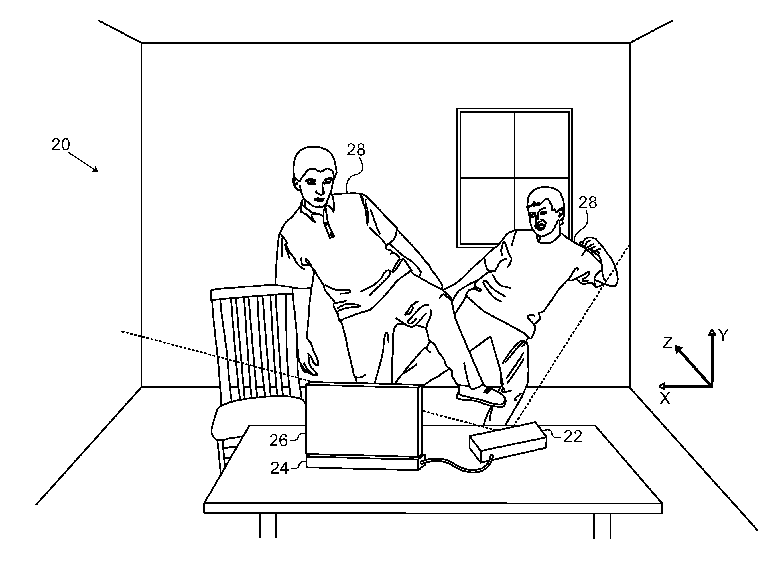
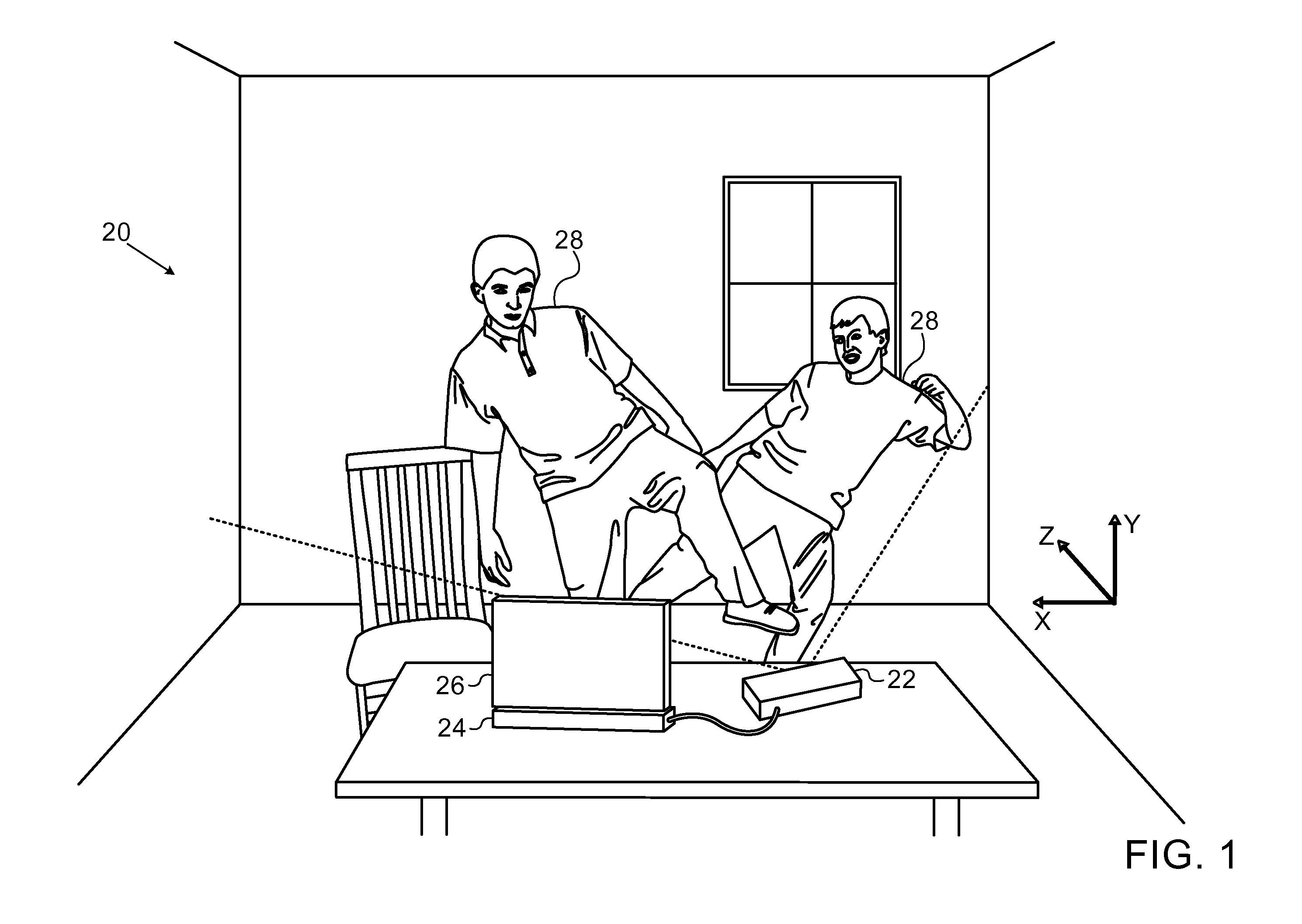
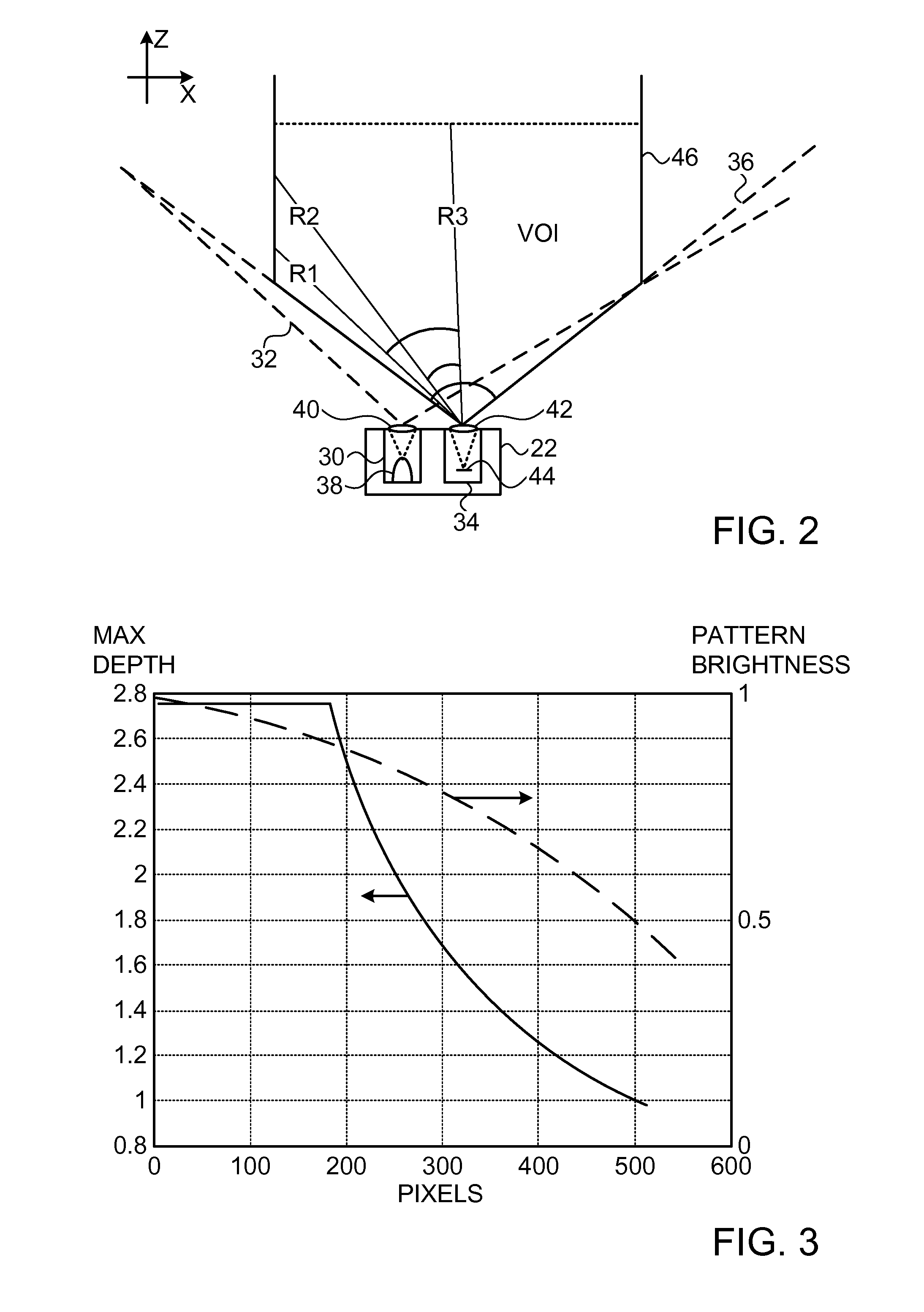
[0017]In creating a depth mapping system, the designer typically attempts to optimize the 3D resolution of the system, including both the effective number of pixels in the map and the number of depth gradations. The resolution is limited, however, by the available resources, including the resolution and signal / noise ratio of the image capture module and, in active depth mapping systems, the power and pattern definition of the illumination module. (The term “active” is used in the context of the present patent application to refer to depth mapping techniques in which a pattern of optical radiation is projected onto an object and an image of the patterned radiation reflected from the object is captured by an imaging device. The pattern may be a spatial pattern, as in patterned illumination imaging systems, or a temporal pattern, as in time-of-flight imaging systems, or it may contain a combination of spatial and temporal patterns.)

[0018]Embodiments of the present invention that are de...


PUM


Abstract

A method for depth mapping includes providing depth mapping resources including an illumination module, which is configured to project patterned optical radiation into a volume of interest containing the object, and an image capture module, which is configured to capture an image of the pattern reflected from the object. A depth map of the object is generated using the resources while applying at least one of the resources non-uniformly over the volume of interest.

Description

CROSS-REFERENCE TO RELATED APPLICATION[0001]This application claims the benefit of U.S. Provisional Patent Application 61 / 309,000, filed Mar. 1, 2010, which is incorporated herein by reference.FIELD OF THE INVENTION[0002]The present invention relates generally to methods and systems for depth mapping, and specifically to optimizing the design and performance of a depth mapping system.BACKGROUND OF THE INVENTION[0003]A number of different methods and systems are known in the art for creating depth maps. In the present patent application and in the claims, the terms “depth map” and “3D map” are used interchangeably to refer to a representation of a scene as a two-dimensional matrix of pixels, in which each pixel corresponds to a respective location in the scene and has a respective pixel value indicative of the distance from a certain reference location to the respective scene location. In other words, the depth map has the form of an image in which the pixel values indicate topograph...

Claims


Application Information

Patent Timeline
IPC IPC(8): H04N13/02
CPCG06F3/005G06F3/011H04N13/0253G06T2207/10016G06T2207/30196G06T7/0057G06T7/521H04N13/254H04N13/271
Inventor SHPUNT, ALEXANDERMOR, ZAFRIR
Owner APPLE INC
Why Eureka
Try Eureka