Power factor correction converter
- Summary
- Abstract
- Description
- Claims
- Application Information
AI Technical Summary
Benefits of technology
Problems solved by technology
Method used
Image

Examples
Embodiment Construction
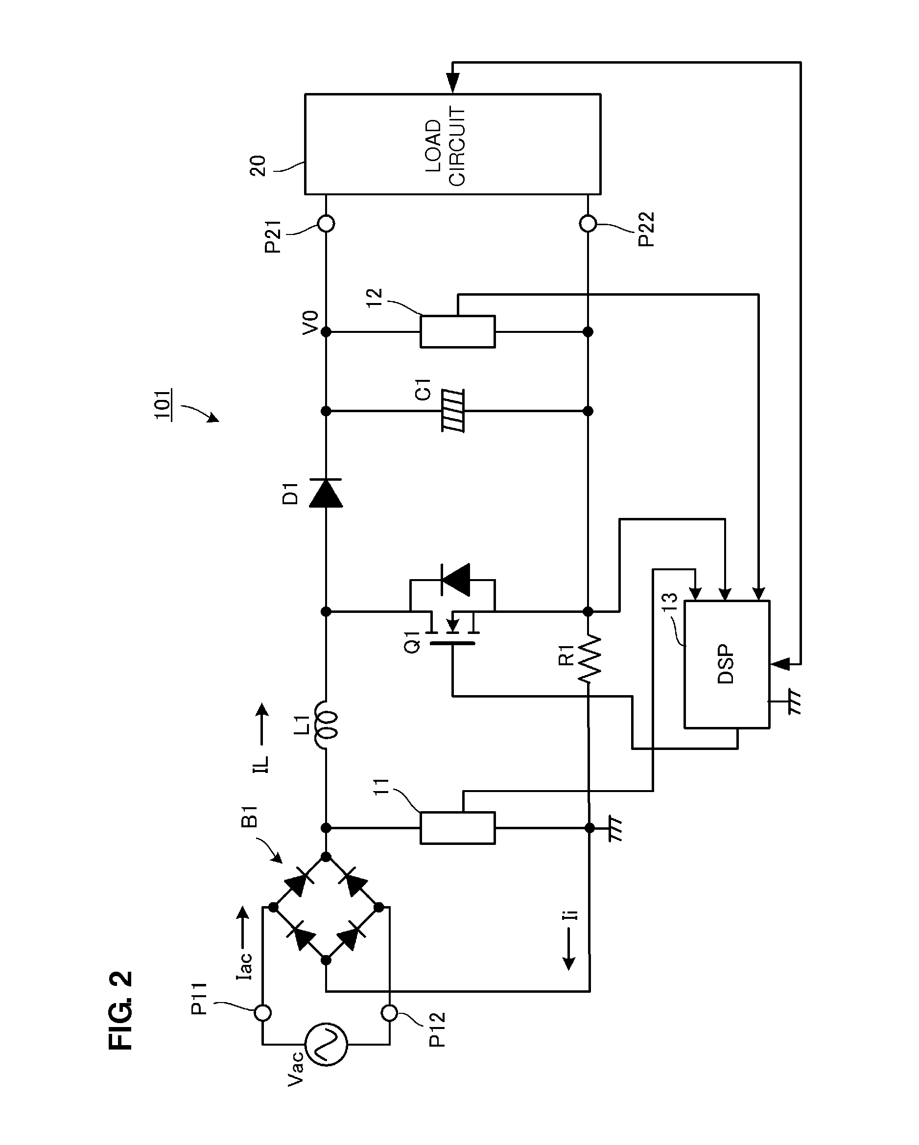
[0036]A PFC converter according to preferred embodiments of the present invention will be described with reference to FIGS. 2 to 8B.
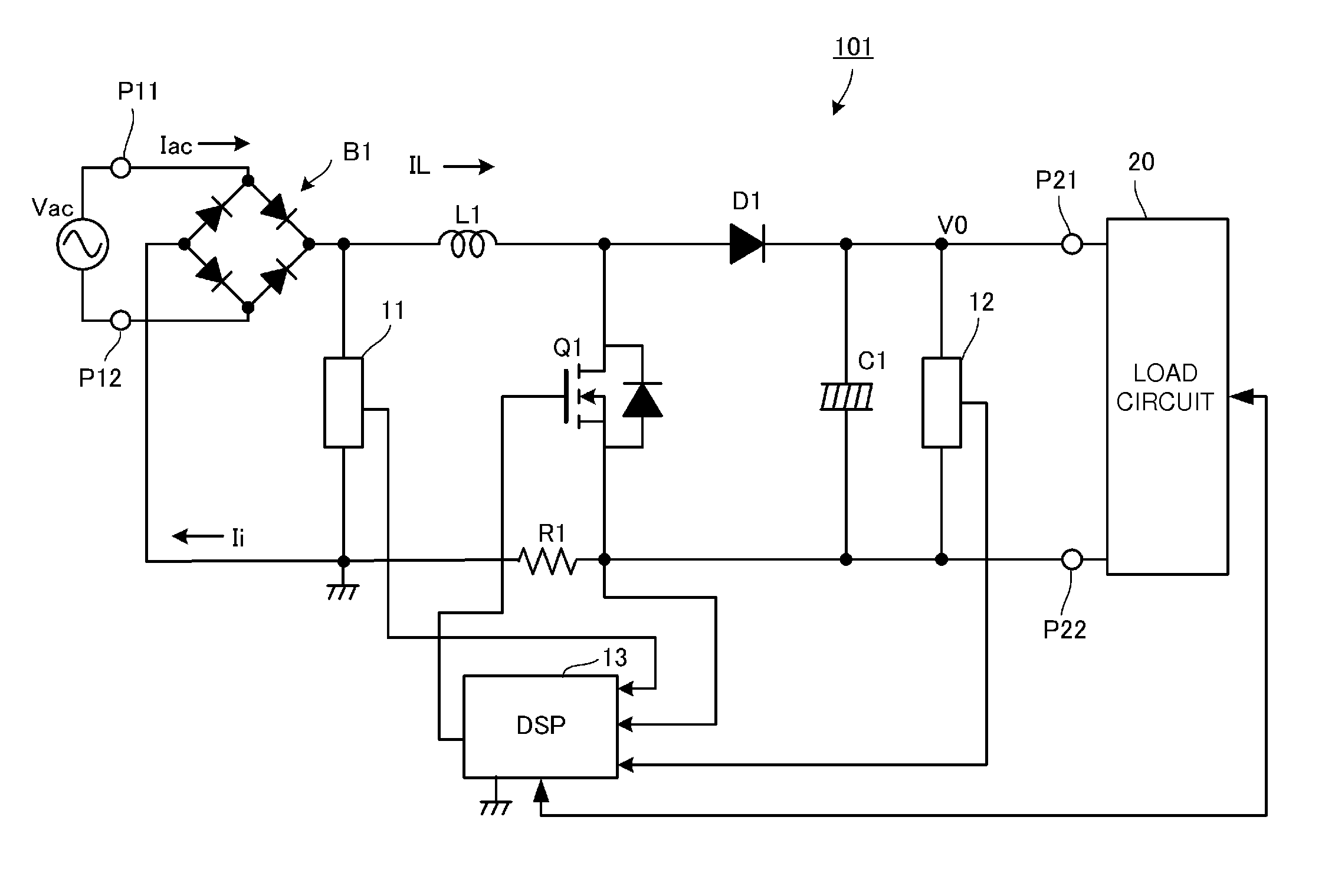
[0037]FIG. 2 is a circuit diagram of a PFC converter 101 according to a preferred embodiment of the present invention. In FIG. 2, numerals P11 and P12 are the input ports of the PFC converter 101, and numerals P21 and P22 are the output ports thereof. An alternating-current input power supply vac, which is preferably a commercial alternating-current power supply, for example, is input into the input port P11 and P12, and a load circuit 20 is connected to the output ports P21 and P22.
[0038]The load circuit 20 is preferably, for example, a circuit including a DC-DC converter and an electronic device that receives power supply therefrom.
[0039]A diode bridge B1, which is a rectifier circuit that full-wave rectifies the alternating-current voltage of the alternating-current input power supply vac, is disposed in the input stage of the PFC converter 101. A se...
PUM
 Abstract
Description
Claims
Application Information
 - R&D
- Intellectual Property
- Life Sciences
- Materials
- Tech Scout
- Unparalleled Data Quality
- Higher Quality Content
- 60% Fewer Hallucinations
Browse by: Latest US Patents, China's latest patents, Technical Efficacy Thesaurus, Application Domain, Technology Topic, Popular Technical Reports.
© 2025 PatSnap. All rights reserved.Legal|Privacy policy|Modern Slavery Act Transparency Statement|Sitemap|About US| Contact US: help@patsnap.com