Signal Generation for Binaural Signals

a binaural signal and signal technology, applied in pseudo-stereo systems, stereophonic arrangments, electrical apparatus, etc., can solve the problems of unnatural sound, unfavorable listening experience, and inability to achieve the effect of reducing the set of channels, reducing the similarity, and stable and pleasant binaural signals

Active Publication Date: 2011-09-01
FRAUNHOFER GESELLSCHAFT ZUR FOERDERUNG DER ANGEWANDTEN FORSCHUNG EV
View PDF15 Cites 102 Cited by
  • Summary
  • Abstract
  • Description
  • Claims
  • Application Information

AI Technical Summary

Benefits of technology

[0015]The first idea underlying the present application is that a more stable and pleasant binaural signal for headphone reproduction may be achieved by differently processing, and thereby reducing the similarity between, at least one of a left and a right channel of the plurality of input channels, a front and a rear channel of the plurality of input channels, and a center and a non-center channel of the plurality of channels, thereby obtaining an inter-similarity reduced set of channels. This inter-similarity reduced set of channels is then fed to a plurality of directional filters followed by respective mixers for the left and the right ear, respectively. By reducing the inter-similarity of channels of the multi-channel input signal, the spatial width of the binaur

Problems solved by technology

Problems occur when a person listens to a stereo signal that is intended for being reproduced by a loud speaker setup via headphones.
It is very likely that the listener would regard the sound as unnatural, awkward, and disturbing as the listener feels that the sound source is located in the head.
Long-term listening to “in-the-head” sound may lead to listening fatigue.
However, since there are many filters necessitated, namely N×2 with N being the number of decoded channels, these directional filters are rather long, such as 20000 filter taps at 44.1 kHz, and the process of filtering is computationally demanding.
However, the listening results achieved thus far s

Method used


Image

  • Signal Generation for Binaural Signals
  • Signal Generation for Binaural Signals
  • Signal Generation for Binaural Signals

Examples


Embodiment Construction

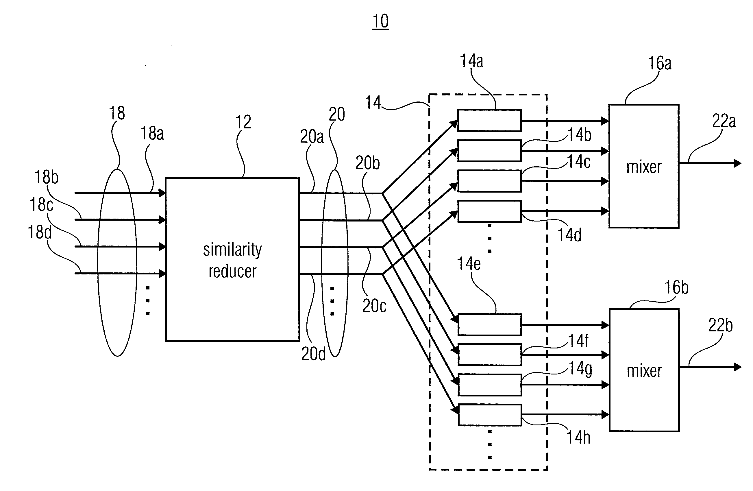
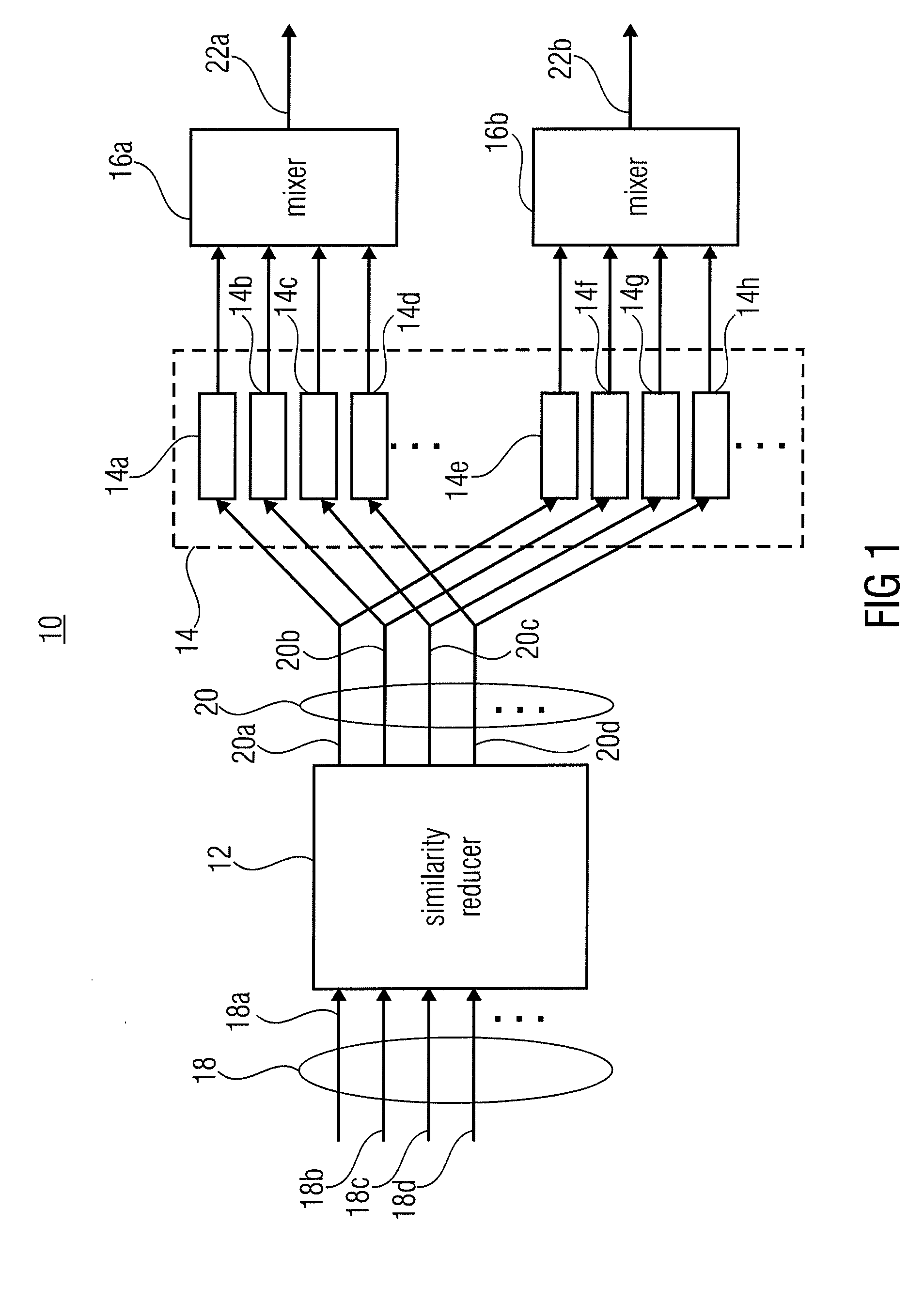
[0033]FIG. 1 shows a device for generating a binaural signal intended, for example, for headphone reproduction based on a multi-channel signal representing a plurality of channels and intended for reproduction by a speaker configuration having a virtual sound source position associated to each channel. The device which is generally indicated with reference sign 10, comprises a similarity reducer 12, a plurality 14 of directional filters 14a-14h, a first mixer 16a and a second mixer 16b.

[0034]The similarity reducer 12 is configured to turn the multi-channel signal 18 representing the plurality of channels 18a-18d, into an inter- similarity reduced set 20 of channels 20a-20d. The number of channels 18a-18d represented by the multi-channel signal 18 may be two or more. For illustration purposes only, four channels 18a-18d have explicitly been shown in FIG. 1. The plurality 18 of channels may, for example, comprise a center channel, a front left channel, a front right channel, a rear l...


PUM


Abstract

A device for generating a binaural signal based on a multi-channel signal representing a plurality of channels and intended for reproduction by a speaker configuration having a virtual sound source position associated to each channel, is described. It includes a correlation reducer for differently processing, and thereby reducing a correlation between, at least one of a left and a right channel of the plurality of channels, a front and a rear channel of the plurality of channels, and a center and a non-center channel of the plurality of channels, in order to obtain an inter-similarity reduced set of channels; a plurality of directional filters, a first mixer for mixing outputs of the directional filters modeling the acoustic transmission to the first ear canal of the listener, and a second mixer for mixing outputs of the directional filters modeling the acoustic transmission to the second ear canal of the listener. According to another aspect, a center level reduction for forming the downmix for a room processor is performed. According to even another aspect, an inter-similarity decreasing set of head-related transfer functions is formed.

Description

CROSS-REFERENCE TO RELATED APPLICATIONS[0001]This application is a continuation of copending International Application No. PCT / EP2009 / 005548, filed Jul. 30, 2009, which is incorporated herein by reference in its entirety, and additionally claims priority from U.S. application Ser. No. 61 / 085,286, filed Jul. 31, 2008, which is incorporated herein by reference in its entirety.BACKGROUND OF THE INVENTION[0002]The present invention relates to the generation of a room reflection and / or reverberation related contribution of a binaural signal, the generation of a binaural signal itself, and the forming of an inter-similarity decreasing set of head-related transfer functions.[0003]The human auditory system is able to determine the direction or directions where sounds perceived come from. To this end, the human auditory system evaluates certain differences between the sound received at the right hand ear and sound received at the left hand ear. The latter information comprises, for example, ...

Claims


Application Information

Patent Timeline
IPC IPC(8): H04R5/00
CPCH04S3/004H04S2420/01H04S2400/01H04S7/30H04S5/00H04S7/00
Inventor MUNDT, HARALDNEUGEBAUER, BERNHARDHILPERT, JOHANNESSILZLE, ANDREASPLOGSTIES, JAN
Owner FRAUNHOFER GESELLSCHAFT ZUR FOERDERUNG DER ANGEWANDTEN FORSCHUNG EV
Why Eureka
Try Eureka