Variable valve device and method of controlling the same

a variable valve and valve control technology, applied in electrical control, machines/engines, non-mechanical valves, etc., can solve the problems of inability to maintain the open state of the air intake valve with a desired degree of opening, inability to prevent the sliding operation of the spool when the variable valve control is being performed, and the initial operation is unstable. , to achieve the effect of smooth sliding, preventing the delay in the sliding operation of the spool when the variable valve control is being performed, and preventing the delay

Inactive Publication Date: 2011-09-08
KOMATSU LTD
View PDF5 Cites 4 Cited by
  • Summary
  • Abstract
  • Description
  • Claims
  • Application Information

AI Technical Summary

Benefits of technology

[0022]According to the first and sixth inventions, the variable valve control is performed after the control valve stabilizing control for sliding the spool of the hydraulic control valve is performed during a period where the air intake valve fully closes the air intake port, allowing the spool of the hydraulic control valve to be smoothly slidable on the slide surface. Thus, delay in the sliding operation of the spool when the variable valve control is being performed can be prevented, and therefore variation in timing for the air intake valve to close due to the delayed operation of the spool can be suppressed.
[0023]Further, according to the second and seventh inventions, the control valve stabilizing control changes a period of time during which the spool is kept on the prevented side so that an oil film may be formed on the slide surface of the hydraulic control valve according to the rotation speed of the engine, and therefore, the spool of the hydraulic control valve can be in a smoothly slidable state on the slide surface regardless of the rotation speed of the engine. Thus, the delay in the sliding operation of the spool of the hydraulic control valve to be performed thereafter can be prevented, and therefore variation in timing for the air intake valve to close due to the delayed operation of the spool can be prevented.
[0024]Further, according to the third and eighth inventions, the control valve stabilizing control is sequentially performed for cylinders of the engine in an order corresponding to a firing order of the cylinders. Thus, the delay in the sliding operation of the spool when the variable valve control is being performed can be prevented for each of the cylinders, and therefore variation in timing for the air intake valve to close due to the delayed operation of the spool can be suppressed.
[0025]Further, according to the fourth and ninth inventions, the variable valve control and the control valve stabilizing control are performed in combination, and the control valve stabilizing control is performed during a period where the variable valve control is not performed. Thus, the valve stabilizing control is performed at a timing not affecting operation of an air intake valve by the variable valve control.
[0026]Further, according to the fifth and tenth inventions, the variable valve control and the control valve stabilizing control are combined, and in performing the variable valve control, the variable valve control is performed after the control valve stabilizing control is performed. Thus, the delay in the sliding operation of the spool when the variable valve control is being performed can be prevented more reliably and therefore variation in timing for the air intake valve to close due to the delayed operation of the spool can be suppressed more reliably.
[0027]Further, according to the first through tenth inventions, the operation of the spool is controlled with a high degree of accuracy. Thus, imperfect combustion and collision between the air intake valve and the piston of the engine due to the variation in timing for the air intake valve to close can be avoided.

Problems solved by technology

As a result, there was a problem that the piston of the hydraulic actuator cannot arrive at a desired position and therefore the open state of the air intake valve cannot be kept with a desired degree of opening.
However, in the solenoid on / off valve disclosed in the Patent document 1, when the OFF state continues, a shortage of oil film occurs in the spool section of the solenoid on / off valve.
As a result, there may be a case in which an initial operation is unstable.
Specifically, after the OFF state of the solenoid on / off valve had continued and at the first on / off operation of the solenoid on / off valve, if the oil film is short in the spool section, then the spool in the spool portion cannot move smoothly.
As a result, compression ratio changes and imperfect combustion might occur.
Further, when a return of the spool is slow (delayed), and timing to fully close the air intake valve is delayed, collision might occur between the air intake valve and the piston of the engine.

Method used


Image

  • Variable valve device and method of controlling the same
  • Variable valve device and method of controlling the same
  • Variable valve device and method of controlling the same

Examples


Embodiment Construction

[0038]An embodiment of a variable valve device and a method of controlling the variable valve device according to the present invention will be described in detail below in reference to the accompanying drawings.

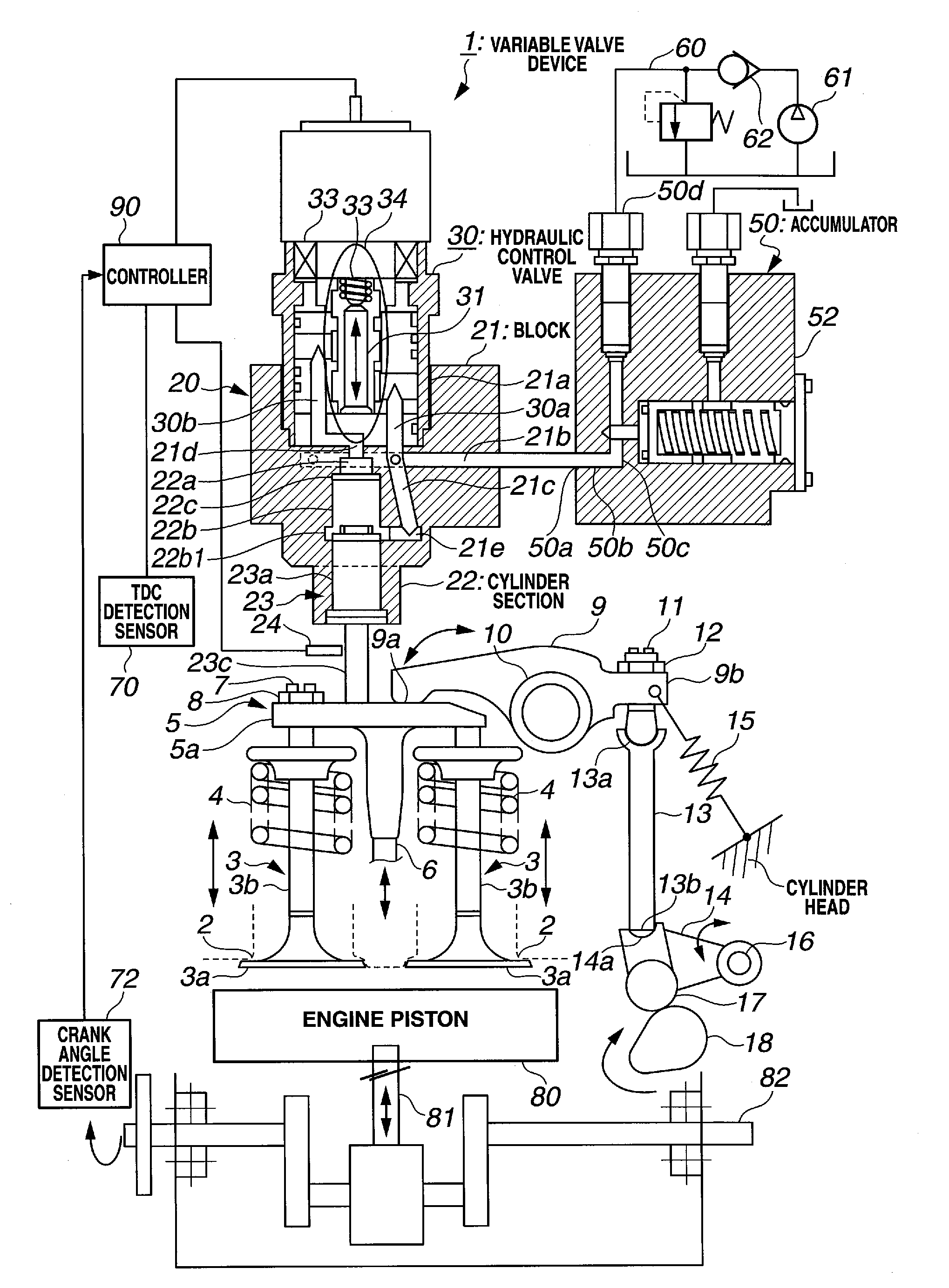
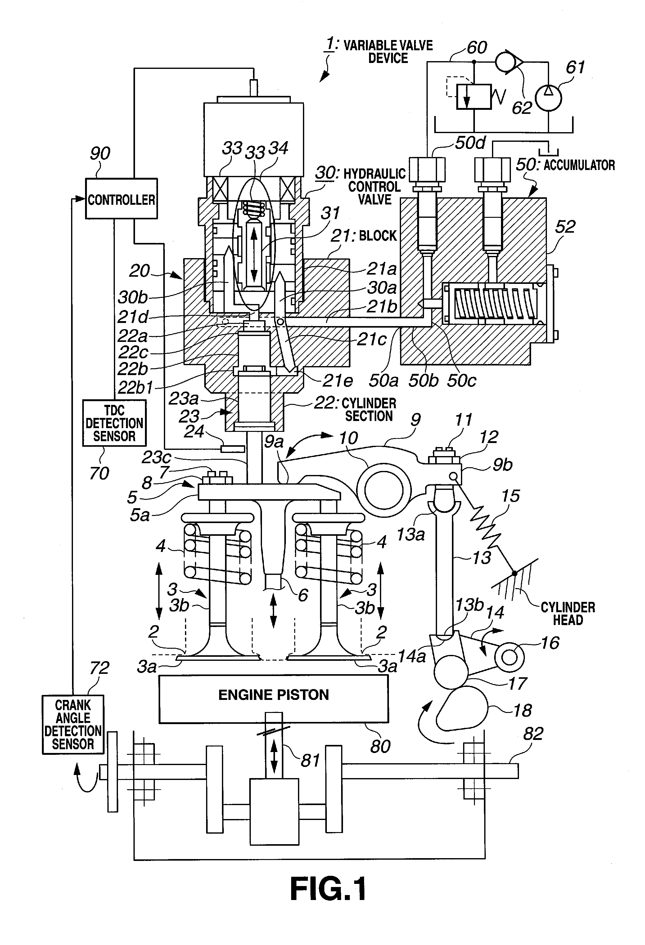
[0039]FIG. 1 a schematic diagram illustrating a variable valve device 1 according to the present invention. Although it is supposed in this embodiment that the variable valve device 1 is applied to a four-cycle diesel engine, and description of this embodiment will be made accordingly, a variable valve device according to the present invention is not limited to this embodiment.

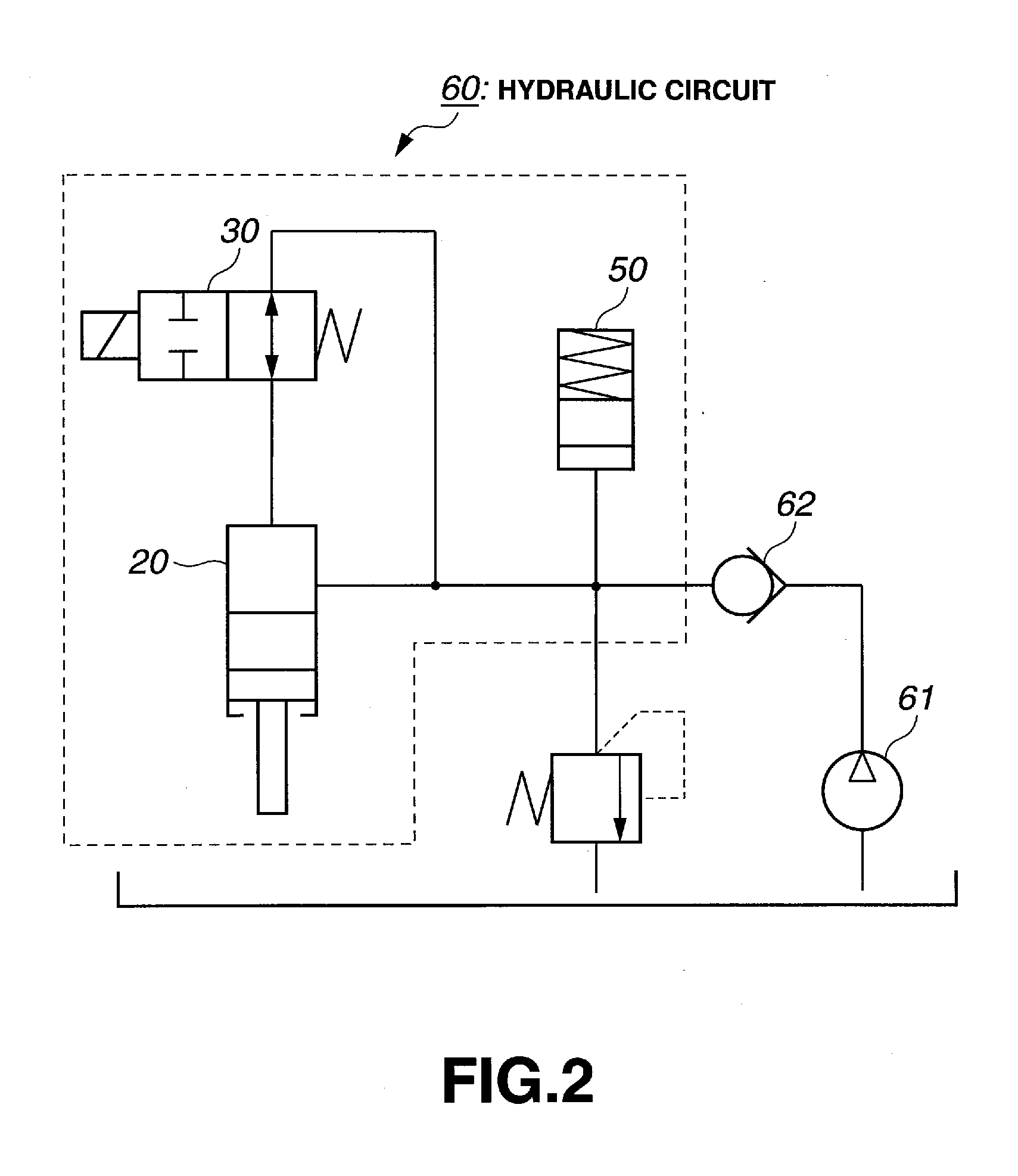
[0040]Referring to FIG. 1, the variable valve device 1 comprises a variable valve device controlling controller (hereinafter simply called “controller”) 90, a gap sensor 24, TDC (Top Dead Center) detection sensor 70, a crank angle detection sensor 72, a hydraulic actuator 20 constituting a hydraulic circuit 60 described later (see FIG. 2), a hydraulic control valve 30, an accumulator 50 and a diesel en...


PUM


Abstract

A variable valve device and a method of controlling the variable valve device, wherein, in order to prevent a shortage of oil film in a spool section, only the spool of a solenoid on/off valve is moved at a timing not affecting operation of an air intake valve, to thereby stabilize operation of the solenoid on/off valve.

Description

CROSS REFERENCE TO RELATED APPLICATIONS[0001]This application is a U.S. national stage application of PCT / JP2009 / 069164 filed on Nov. 11, 2009, and claims priority to, and incorporates by reference, Japanese Patent Application No. 2008-297229 filed on Nov. 20, 2008.TECHNICAL FIELD[0002]The present invention relates to a variable valve device and a method of controlling the variable valve device.BACKGROUND ART[0003]As an engine to be mounted on a vehicle, there has been an engine that is provided with a variable valve device for adjusting an air-intake or exhaust volume by controlling an open / close timing for the air intake valve and the exhaust valve according to operating conditions of the engine.[0004]There has been such a variable valve device that uses an electric motor or a hydraulic pressure. In a hydraulic variable valve device that is driven by hydraulic pressure, there has been one in which a variable valve is operated by controlling a flow of operating oil.[0005]For exampl...

Claims


Application Information

Patent Timeline
Patent Type & Authority Applications(United States)
IPC IPC(8): F01L9/02F01L1/34F01L9/10
CPCF01L1/267F01L9/02F01L13/0015F01L2001/34443Y02T10/142F02D13/0226F02D13/0269F02D41/20F02D2041/001F01L2013/0089Y02T10/12F01L9/10
Inventor SATO, ETSUROTACHIBANA, HIDEAKIHISADA, YOUHEIOHTA, KAZUO
Owner KOMATSU LTD
Why Eureka
Try Eureka