Catalytic converter fastening for a combustion engine

a technology for catalytic converters and combustion engines, which is applied in the direction of machines/engines, other domestic objects, machine supports, etc., can solve the problems of high assembly costs, additional storage costs, and complicated assembly of engine block brackets, so as to reduce heat connection, improve cooling air flow, and simplify engine block bracket assembly

Inactive Publication Date: 2011-09-08
GM GLOBAL TECH OPERATIONS LLC
View PDF7 Cites 13 Cited by
  • Summary
  • Abstract
  • Description
  • Claims
  • Application Information

AI Technical Summary

Benefits of technology

[0013]In addition, it is provided that elongated holes in the engine block bracket are open vertically downwards and the engine block bracket can be pushed onto the connecting elements on the engine block with the elongated holes open towards the bottom. This has the advantage that the assembly of the engine block bracket is simplified more so since inserting connecting elements through corresponding bores of the engine block bracket provided with compensating washers is not required.
[0014]In addition, it is provided that on the engine block bracket space-holding molded-on passages or welded-on bushings are arranged in the region of fastening openings of the engine block bracket. These welded-on bushings or molded-on passages allow reducing the heat connection between engine block bracket and engine block. Furthermore, a spacing between engine block and engine block bracket is created that makes possible an improved cooling air flow. For compensating manufacturing tolerances of the catalytic converter fastening and for compensating heat expansion differences cylindrical compensating elements of a plastic or a metal alloy are arranged in the space-holding molded-on passages or welded-on bushings.

Problems solved by technology

However, this is not always the case, particularly not if it is an exhaust manifold catalytic converter with which the catalytic converter is fixed on the exhaust manifold, while the catalytic converter for example is arranged vertically and parallel to the engine block and without flange merges into an exhaust pipe of an exhaust system.
A further disadvantage of the known catalytic converter fastening comprises in that it is composed of at least two parts, namely an engine block bracket and a catalytic converter bracket, which are held together via connecting screws, so that a plurality of individual elements is required in order to assemble this catalytic converter fastening.
Through the multiplicity of individual parts for this catalytic converter fastening, additional storage costs are incurred in addition to the high assembly costs in order to keep the appropriate parts in stock and ready for the production.

Method used


Image

  • Catalytic converter fastening for a combustion engine
  • Catalytic converter fastening for a combustion engine
  • Catalytic converter fastening for a combustion engine

Examples


first embodiment

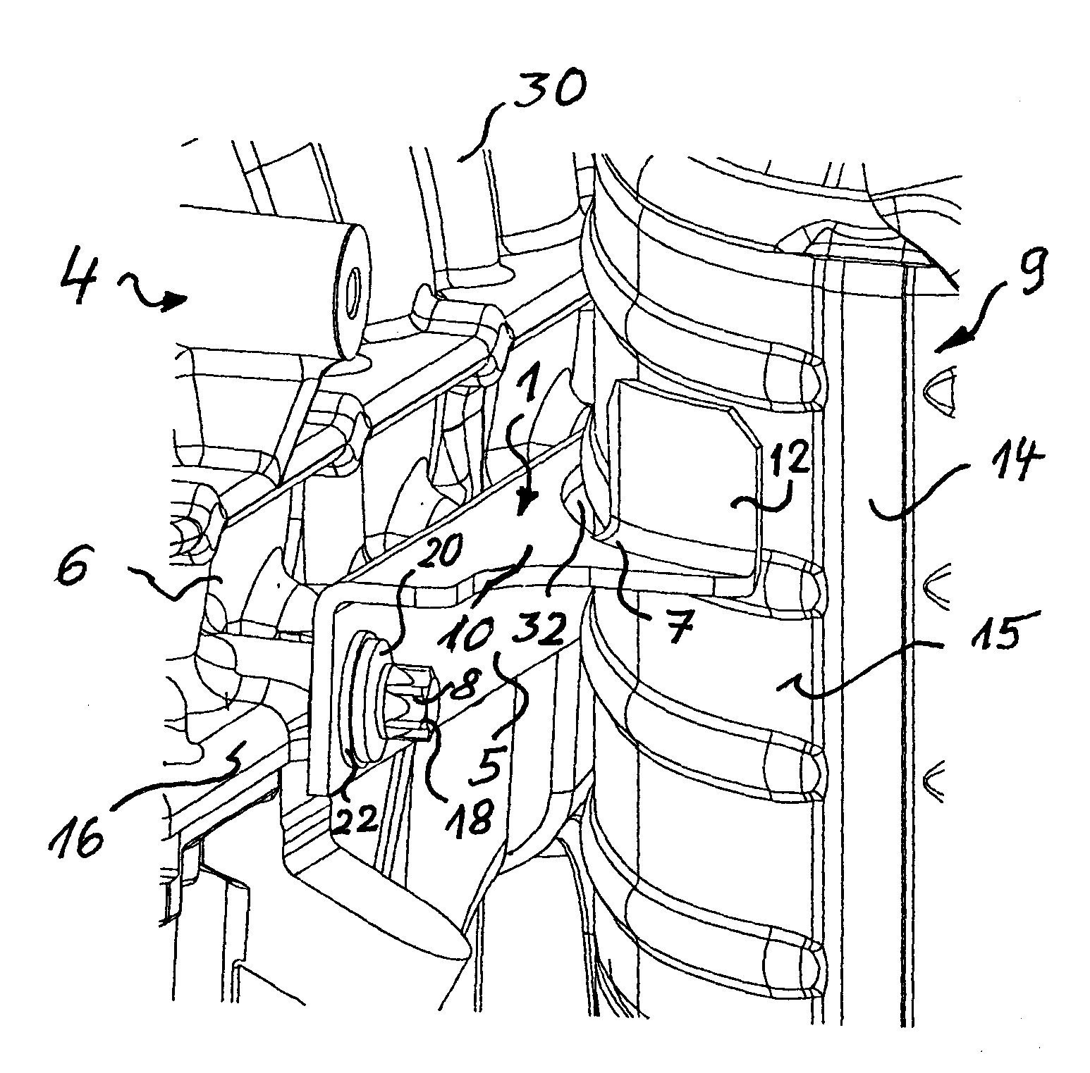
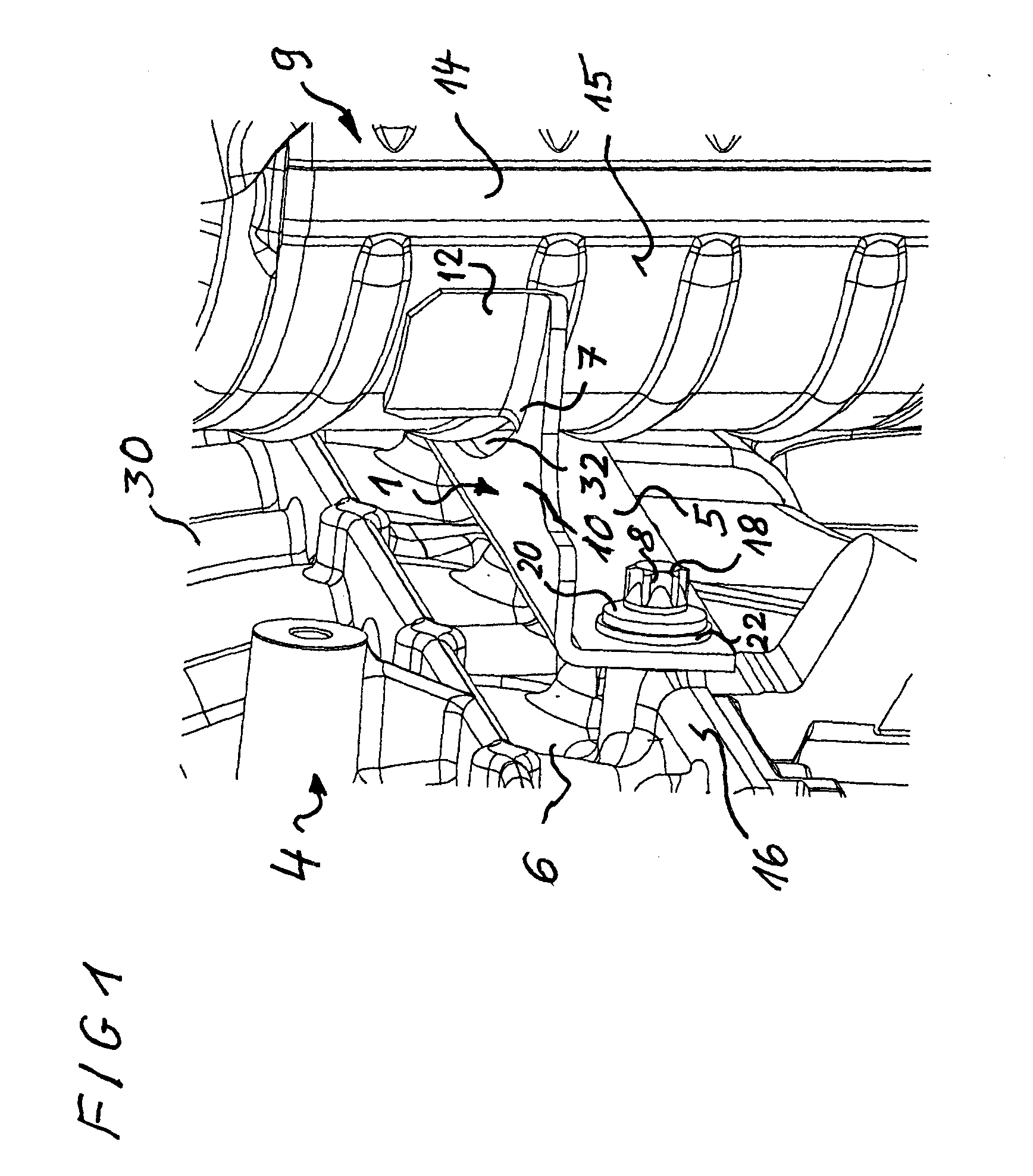
[0023]FIG. 1 shows a schematic perspective part view of a catalytic converter 9, which with the help of a catalytic converter fastening 1 according to the subject of the application is fixed on an engine block 6. The engine block 6 belongs to a combustion engine 4, which above the engine block 6 comprises a cylinder head 30 to which an exhaust manifold that is not shown here is connected, whose exhaust gases are initially conducted into the catalytic converter 9. Accordingly, the exhaust gases are extremely hot and the catalytic converter 9 has a reaction temperature in its interior of approximately 800° C. The engine block 6 by comparison is water-cooled and has an outer operating temperature below approximately 300° C.

[0024]Next to the unavoidable manufacturing tolerances for a catalytic converter fastening 1 problems of the different thermal expansions of engine block 6, catalytic converter 9 and exhaust manifold have to be solved by such a catalytic converter fastening 1 above a...

third embodiment

[0037]FIG. 5 shows a schematic perspective view of the catalytic converter fastening 3 according to FIG. 5 from a changed viewing angle. Components with same functions as in the preceding figures are marked with the same reference characters and are not separately discussed. From the viewing direction shown in FIG. 5 a chamfer 29 is visible on the compensating element 31 which facilitates inserting or screwing-in of the compensating element 31 in the fastening opening 28. While on the right side the connecting element 8 is shown expanded, the assembly is shown on the left side of the figure wherein the thread of the tensile screw 21 protrudes out of the cylinder-shaped compensating element 31. The end of the cylinder-shaped compensating element 31 in turn protrudes out of the welded-on bushing 26 which itself stands away from the engine block bracket 5. Thus with the help of this third embodiment a wide gap can be created between engine block and engine block bracket 5 and varied in...


PUM


Abstract

A catalytic converter fastening is provided for a combustion engine. The catalytic converter fastening includes, but is not limited to an engine block bracket that is releasably connected to an engine block. The engine block bracket fixes the catalytic converter at a distance to the engine block. A catalytic converter support is materially connected to the catalytic converter, and connecting elements releasably connect the engine block bracket to the engine block. The catalytic converter support comprises at least one arm angled-off towards the engine block bracket, while on the arm at least one angled-off strap is arranged. The strap is materially connected to a catalytic converter housing. Here, the catalytic converter fastening of engine block bracket and catalytic converter support is of the unitary type.

Description

CROSS-REFERENCE TO RELATED APPLICATION[0001]This application claims priority to German Patent Application No. 102010010397.7, filed Mar. 5, 2010, which is incorporated herein by reference in its entirety.TECHNICAL FIELD[0002]The technical field relates to a catalytic converter fastening for a combustion engine. A catalytic converter fastening comprises an engine block bracket that is releasably connected to an engine block. The engine block bracket fixes the catalytic converter at a distance to the engine block.BACKGROUND[0003]A catalytic converter fastening is known from the publication DE 10 2004 023 585 B4 for a combustion engine. In addition to this, the known catalytic converter fastening comprises an engine block bracket (for fastening to a combustion engine) and a catalytic converter bracket for fastening to a catalytic converter. Finally, the catalytic converter fastening comprises connecting means for connecting engine bracket and catalytic converter bracket. The catalytic ...

Claims


Application Information

Patent Timeline
Patent Type & Authority Applications(United States)
IPC IPC(8): F16M13/02
CPCB60K13/04F01N2450/24F01N13/1855F01N13/1805
Inventor LOEBIG, ARNOLD
Owner GM GLOBAL TECH OPERATIONS LLC
Why Eureka
Try Eureka