Light-Emitting Element, Light-Emitting Device, Electronic Device, and Lighting Device

a technology of light-emitting elements and electronic devices, which is applied in the direction of thermoelectric devices, solid-state devices, other domestic articles, etc., can solve the problems of light-emitting elements and reduce the driving voltage, and achieve the effects of reducing power consumption, increasing the driving voltage, and preventing the interaction between the first layer and the third layer

Active Publication Date: 2011-09-08
SEMICON ENERGY LAB CO LTD
View PDF28 Cites 13 Cited by
  • Summary
  • Abstract
  • Description
  • Claims
  • Application Information

AI Technical Summary

Benefits of technology

[0032]In the light-emitting element according to the first embodiment of the present invention, an increase of the driving voltage can be suppressed by the second layer. The second layer provided between the first layer and the third layer can prevent formation of a pn junction and formation of a depletion layer. In addition, interaction between the first layer and the third layer can be prevented. Further, light-emitting devices, electronic devices and lighting devices with less power consumption can be provided by including the light-emitting element.

Problems solved by technology

Light-emitting elements have various problems, one of which is how to reduce the driving voltage.

Method used


Image

  • Light-Emitting Element, Light-Emitting Device, Electronic Device, and Lighting Device
  • Light-Emitting Element, Light-Emitting Device, Electronic Device, and Lighting Device
  • Light-Emitting Element, Light-Emitting Device, Electronic Device, and Lighting Device

Examples


embodiment 1

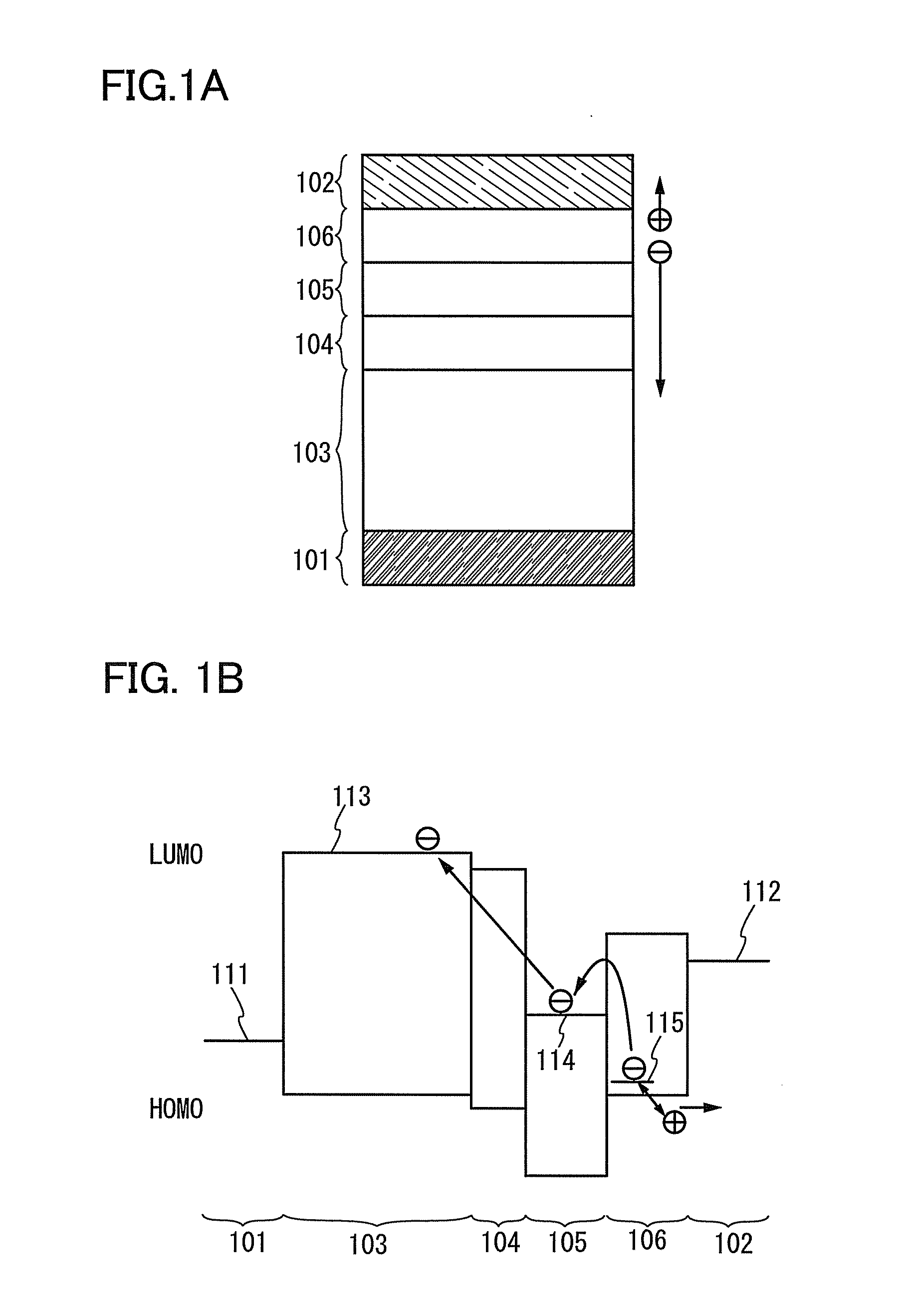
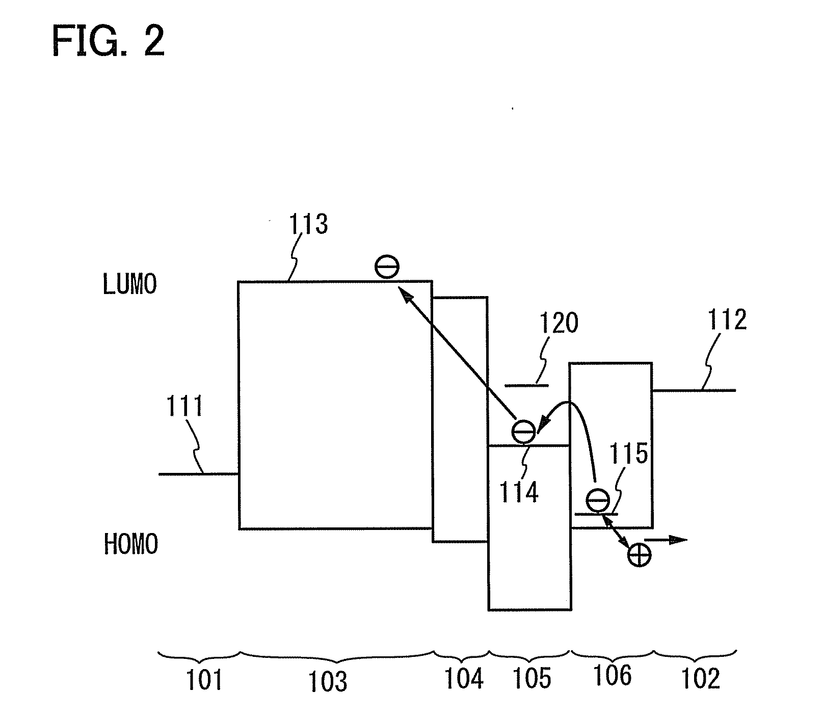
[0052]In Embodiment 1, an element structure of a light-emitting element according to one embodiment of the present invention will be described with reference to FIGS. 1A and 1B and FIG. 2.

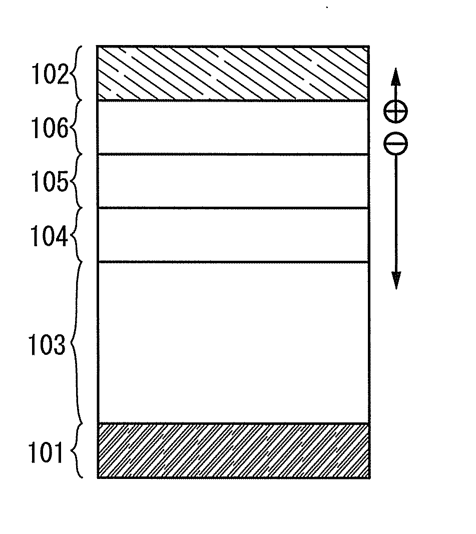
[0053]In a light-emitting element illustrated in FIG. 1A, an EL layer 103 including a light-emitting region is provided between a pair of electrodes (an anode 101 and a cathode 102), and a first layer 106, a second layer 105, and a third layer 104 are stacked in this order from the cathode 102 side between the cathode 102 and the EL layer 103.

[0054]The first layer 106 is provided between the cathode 102 and the second layer 105, and in contact with the cathode 102 and with the second layer 105. The first layer 106 contains a substance having a hole-transport property and an accepter substance with respect to the substance having a hole-transport property and serves as a charge generation region. Holes and electrons are considered to be generated in such a manner that the substance having a hole-tra...

embodiment 2

[0110]In Embodiment 2, an example of the light-emitting element described in Embodiment 1 will be described with reference to FIGS. 3A and 3B.

[0111]In a light-emitting element shown in FIG. 3A, the EL layer 103 including a light-emitting region is provided between the pair of electrodes (the anode 101 and the cathode 102), and the first layer 106 which is a charge generation region, the second layer 105 which is an electron relay layer, and the third layer 104 which is an electron injection buffer are stacked in this order from the cathode 102 side between the cathode 102 and the EL layer 103.

[0112]The same materials described in Embodiment 1 can be used for the anode 101, the cathode 102, the EL layer 103, the first layer 106, and the second layer 105.

[0113]As a substance used for the third layer 104, the following substances having a high electron-injection property can be given as examples: alkali metals such as lithium (Li) and cesium (Cs); alkaline-earth metals such as magnesiu...

embodiment 3

[0121]In Embodiment 3, an example of the light-emitting element described in Embodiment 1 will be described with reference to FIGS. 4A and 4B.

[0122]In a light-emitting element shown in FIG. 4A, the EL layer 103 including a light-emitting region is provided between the pair of electrodes (the anode 101 and the cathode 102), and the first layer 106 which serves as a charge generation region, the second layer 105 which serves as an electron relay layer, and the third layer 104 which serves as an electron injection buffer are stacked in this order from the cathode 102 side between the cathode 102 and the EL layer 103. The third layer 104 contains a substance having an electron-transport property and a donor substance.

[0123]In the third layer 104, a donor substance is preferably added so that the mass ratio thereof to the substance having an electron-transport property is greater than or equal to 0.001:1 and less than or equal to 0.1:1. Accordingly, the function as an electron-injection ...


PUM


Abstract

A light-emitting element includes an EL layer between an anode and a cathode, and a first layer, a second layer, and a third layer between the cathode and the EL layer. The first layer provided between the cathode and the second layer is in contact with the cathode and the second layer, and includes a substance having a hole-transport property and an acceptor substance. The second layer provided between the first layer and the third layer is in contact with the first layer and the third layer, and includes a phthalocyanine-based material. The third layer provided between the second layer and the EL layer is in contact with the second layer and the EL layer, and includes an alkali metal, an alkaline-earth metal, a rare-earth metal, an alkali metal compound, an alkaline-earth metal compound, or a rare-earth metal compound.

Description

BACKGROUND OF THE INVENTION[0001]1. Field of the Invention[0002]The present invention relates to a light-emitting element including an electroluminescence (also referred to as EL) layer (the element also refereed to as an EL element), a light-emitting device including the light-emitting element, and an electronic device and a lighting device each including the light-emitting device.[0003]2. Description of the Related Art[0004]An EL element includes a pair of electrodes and an EL layer provided therebetween. A voltage is applied to the pair of electrodes, so that light is emitted from the EL layer. The EL layer is formed using an organic compound.[0005]Light emission mechanism of the EL element will be described. Upon applying voltage to the pair of electrodes, electrons injected from the cathode and holes injected from the anode are recombined in a light-emission center of the EL layer. As a result of the recombination, energy is released so that light is emitted. Light emission is ...

Claims


Application Information

Patent Timeline
Patent Type & Authority Applications(United States)
IPC IPC(8): H01L51/54
CPCH01L51/0072H01L51/0078H01L51/5092H01L51/5068H01L51/506Y10S428/917H10K85/311H10K85/6572H10K50/157H10K50/155H10K50/171H10K50/156
Inventor NOWATARI, HIROMISEO, SATOSHI
Owner SEMICON ENERGY LAB CO LTD
Why Eureka
Try Eureka