

Sliding component
a technology of sliding components and components, applied in the direction of engine components, mechanical devices, engine seals, etc., can solve the problems of unstable cavitation behavior, unstable behavior of liquid phase and gas phase, and extremely unstable behavior of phase formed between sliding surfaces
- Summary
- Abstract
- Description
- Claims
- Application Information
AI Technical Summary
Benefits of technology
Problems solved by technology
Method used
Image

Examples
first embodiment
[0053]A sliding component according to a first embodiment of the invention will be described with reference to FIGS. 1 to 12. In the first embodiment, the case in which a component constituting a mechanical seal is the sliding component will be described by way of example.
[0054]
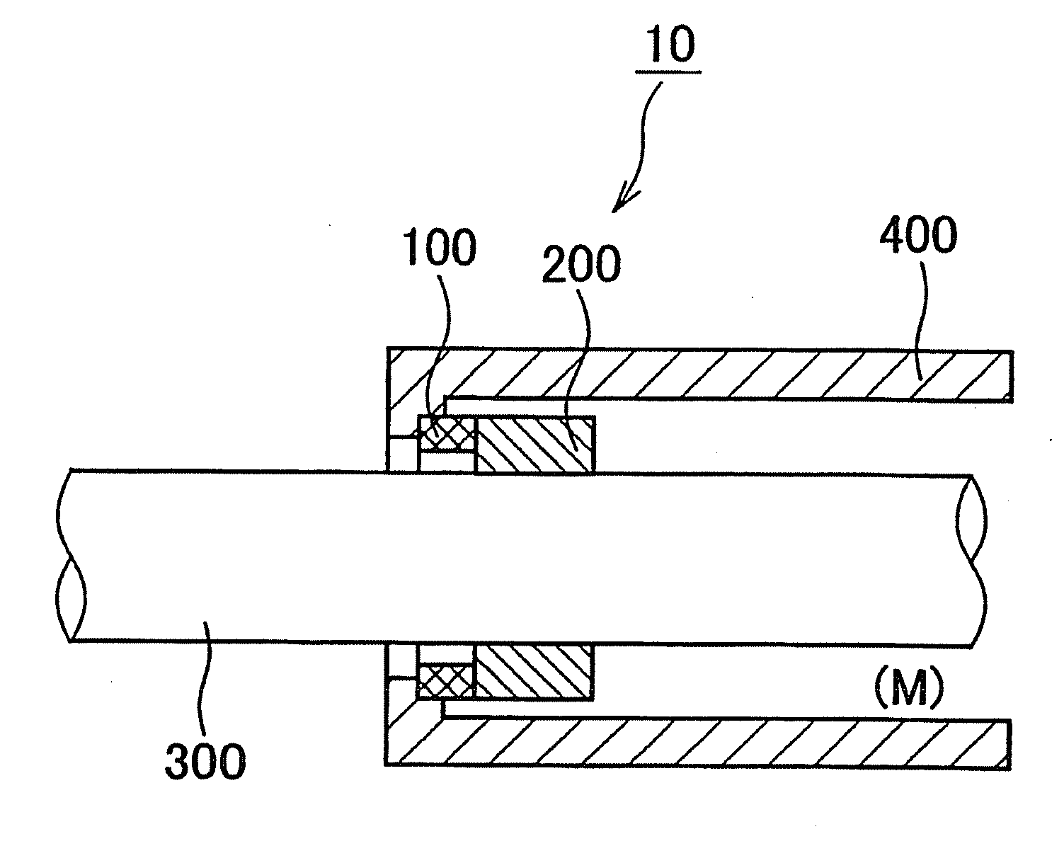
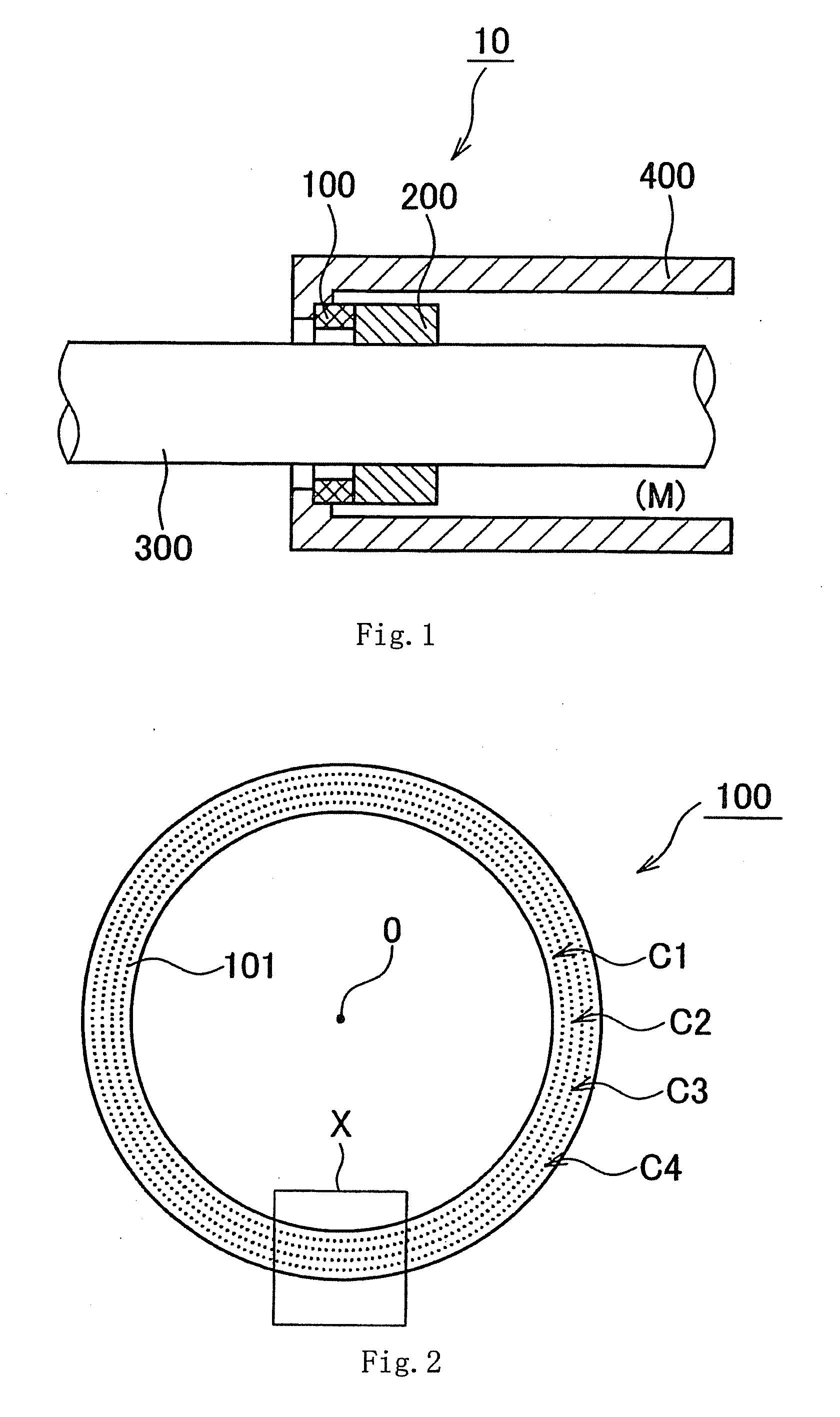
[0055]The mechanical seal to which the sliding component of the first embodiment is applied will be described with reference to FIG. 1. FIG. 1 is a schematically sectional view illustrating a usage state of a mechanical seal according to an embodiment of the invention.
[0056]A mechanical seal 10 is provided to prevent leakage of a liquid (sealed fluid) M sealed in an annular gap between a rotation shaft 300 and a housing 400 in which the rotation shaft 300 is inserted. The mechanical seal 10 includes an annular first sliding component 100 that is fixed onto an inner circumference side of the housing 400 and an annular second sliding component 200 that is fixed to the rotation shaft 300. Because the second slid...
second embodiment
[0100]FIGS. 13 to 17 illustrate a sliding component according to a second embodiment of the invention. In the configuration of the first embodiment, the dimples are disposed so as to be arrayed on the virtual circumferences. In the configuration of the second embodiment, the dimples are disposed so as to be arrayed on a virtual spiral. Because the configuration and the action except the disposition of the dimples are identical to those of the first embodiment, the description of the identical constituent will not be repeated as appropriate.
[0101]FIG. 13 is a plan view of the sliding component (first sliding component) of the second embodiment. FIG. 14 is a partially enlarged view of the sliding component (first sliding component) of the second embodiment. FIG. 14 is an enlarged view of an X portion in FIG. 13. FIG. 15 is a plan view schematically illustrating the state of the sliding surface in the sliding component (first sliding component) of the second embodiment.
[0102]In the sec...
third embodiment and fourth embodiment
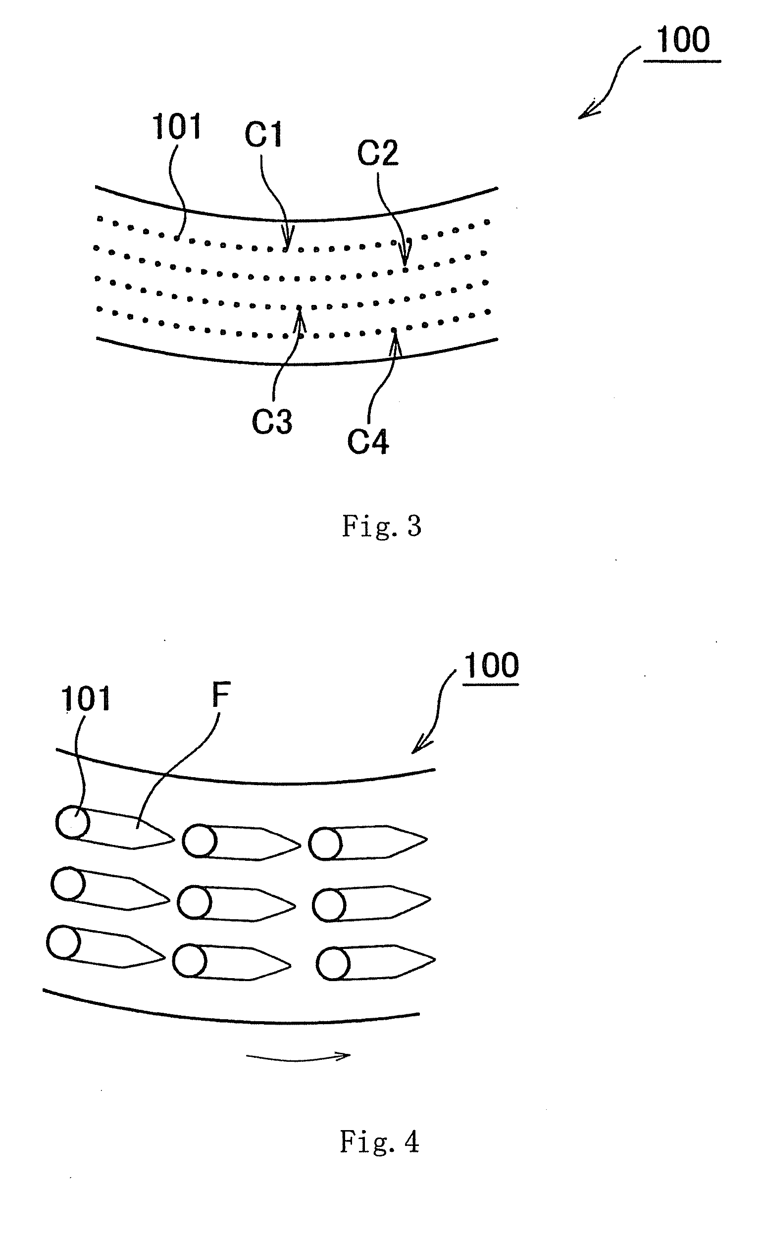
[0112]As described above, the dimples of the first and second embodiments do not have load support capability because the gas phase is formed on the dimple array. Therefore, the load supporting region is reduced in the sliding surface as the number of dimples increases. A surface pressure increases when the number of dimples increases excessively. As a result, a limit at which the lubricating film (film formed with the liquid) can be retained is lowered. Accordingly, the number of dimples is desirably determined such that the lubricating film is stably formed by positioning the gas phase and the liquid phase, and the number of dimples is desirably minimized within the range in which the leakage of the sealed fluid can be prevented such that the load supporting region is secured.
[0113]For example, as illustrated in FIGS. 18 and 19, it is preferable that the region where the dimples retaining the gas phase are arrayed is limited to a given range similarly to the first and second embod...
PUM
 Abstract
Description
Claims
Application Information