
Light guide plate and liquid crystal display device using the same

a technology of liquid crystal display device and light guide plate, which is applied in the direction of lighting and heating apparatus, mechanical equipment, instruments, etc., can solve the problems of light that the polarizer blocks are absorbed by the polarizer, and another light loss factor, and achieve the effect of reducing light loss

Active Publication Date: 2011-09-08
PANASONIC LIQUID CRYSTAL DISPLAY CO LTD +1
View PDF5 Cites 0 Cited by
  • Summary
  • Abstract
  • Description
  • Claims
  • Application Information

AI Technical Summary

Benefits of technology

[0007]It is an object of the present invention to provide a light guide plate capable of reducing light loss and a liquid crystal display device using the same.
[0008](1) A light guide plate according to the present invention for reflecting incident light from an end surface of the light guide plate in an inside to obtain surface emission from a front surface thereof, includes protrusions and recesses which are formed on one of the front surface and a rear surface on an opposite side of the front surface, in which: the protrusions and recesses are formed of a shape in which a plurality of first mountain-range shapes and a plurality of second mountain-range shapes are combined, the plurality of first mountain-range shapes each including a first ridge continuing along a first direction, which is a direction toward the inside from the end surface, the plurality of second mountain-range shapes each including a second ridge continuing along a second direction intersecting with the first direction; each of the plurality of first mountain-range shapes includes a pair of first side surfaces on both sides of the first ridge; and each of the plurality of second mountain-range shapes includes a pair of second side surfaces on both sides of the second ridge. According to the present invention, it was revealed from an experiment by the inventors that the formation of the first mountain-range shapes on the rear surface enables the increase in P-polarized light in the exit light from the front surface of the light guide plate. The P-polarized light is lower in reflectivity than the S-polarized light and accordingly has a smaller component which reflects off an interface on the front surface side of the light guide plate to remain in the inside thereof, and hence the light loss can be reduced.

Problems solved by technology

Further, light that the polarizer blocks is absorbed by the polarizer even if the light exits from the light guide plate.
This is another light loss factor.

Method used


Image

  • Light guide plate and liquid crystal display device using the same
  • Light guide plate and liquid crystal display device using the same
  • Light guide plate and liquid crystal display device using the same

Examples


Embodiment Construction

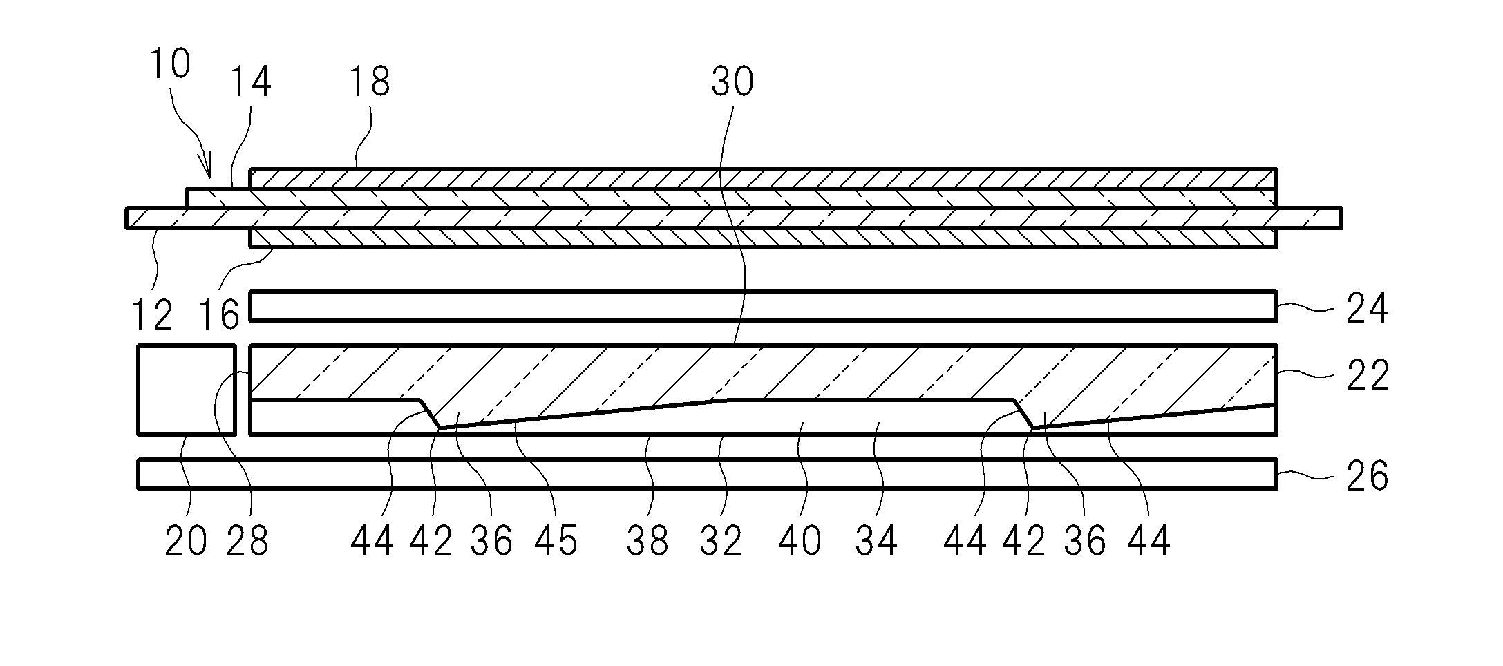
[0025]Hereinafter, an embodiment of the present invention is described with reference to the accompanying drawings. FIG. 1 is an exploded view illustrating an outline of a liquid crystal display device according to the embodiment of the present invention.

[0026]The liquid crystal display device includes a liquid crystal display panel 10. The liquid crystal display panel 10 includes a pair of substrates 12 and 14 made of glass or the like, and liquid crystal (not shown) sandwiched therebetween. The liquid crystal display panel 10 includes polarizers 16 and 18 outside the pair of substrates 12 and 14, respectively.

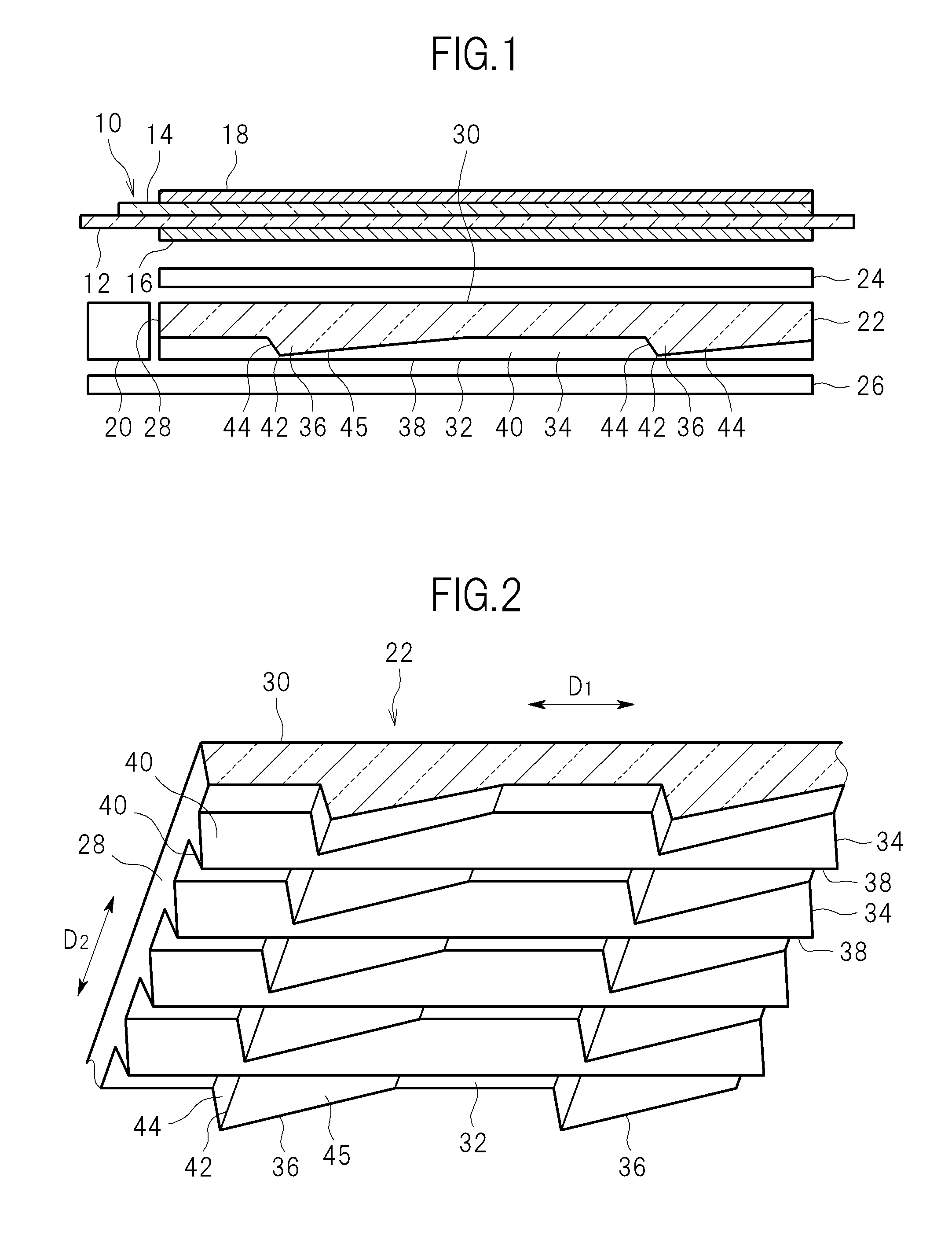
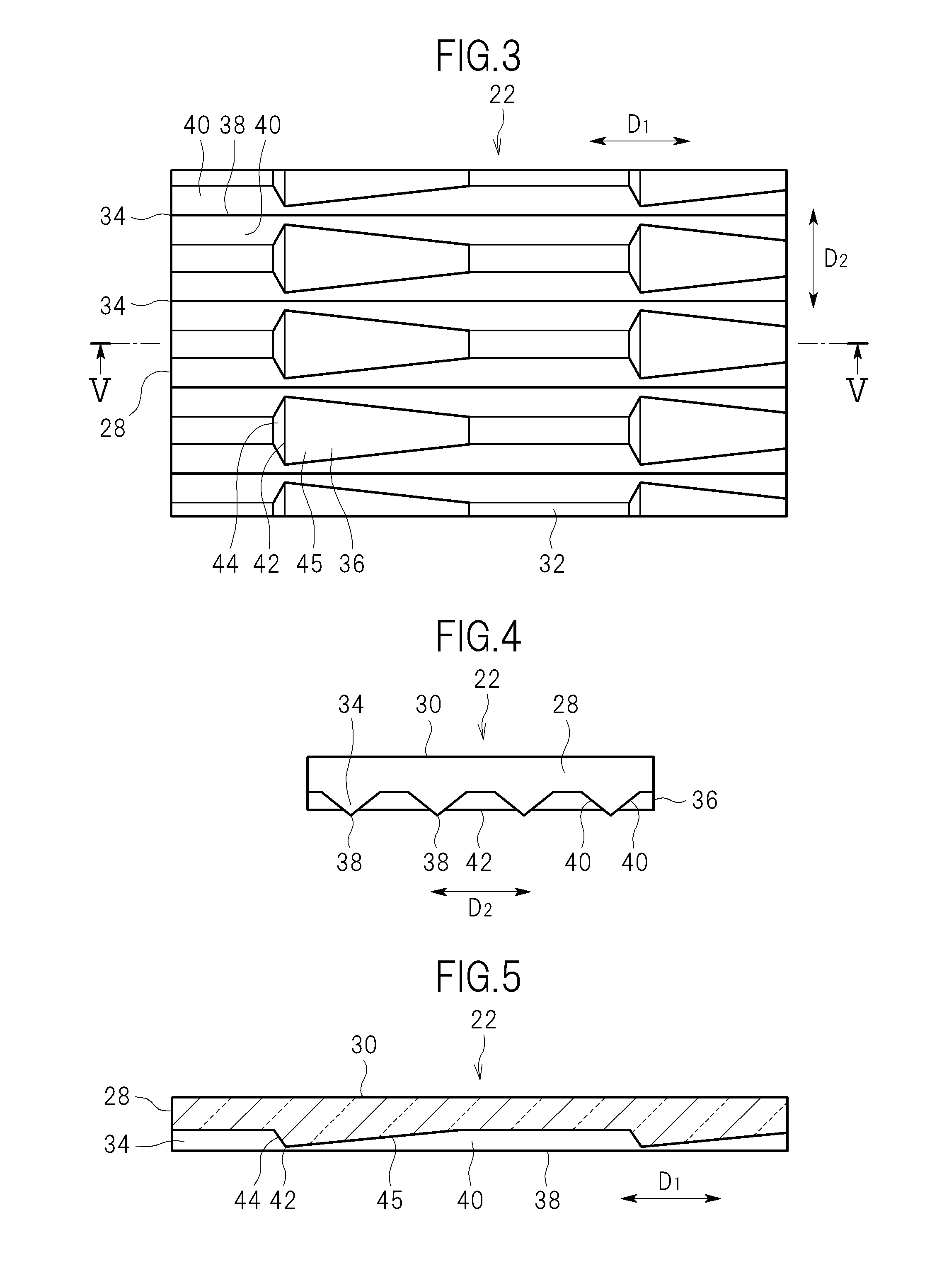
[0027]The liquid crystal display device includes a light source 20. The light source 20 is a point light source or a linear light source such as a light emitting diode (LED), and is converted into a planar light source by a light guide plate 22. The liquid crystal display device includes an optical sheet 24. The optical sheet 24 is disposed between the liquid crystal display ...


PUM


Abstract

A light guide plate is for reflecting incident light from an end surface thereof in an inside to obtain surface emission from a front surface thereof. The light guide plate includes protrusions and recesses formed on one of the front surface and a rear surface on an opposite side of the front surface. The protrusions and recesses are formed of a shape in which first mountain-range shapes each including a first ridge continuing along a first direction, which is a direction toward the inside from the end surface, and second mountain-range shapes each including a second ridge continuing along a second direction intersecting with the first direction are combined. Each first mountain-range shape includes a pair of first side surfaces on both sides of the first ridge. Each second mountain-range shape includes a pair of second side surfaces on both sides of the second ridge.

Description

CROSS-REFERENCE TO RELATED APPLICATION[0001]The present application claims priority from Japanese application JP 2010-044947 filed on Mar. 2, 2010, the content of which is hereby incorporated by reference into this application.BACKGROUND OF THE INVENTION[0002]1. Field of the Invention[0003]The present invention relates to a light guide plate and a liquid crystal display device using the same.[0004]2. Description of the Related Art[0005]In a liquid crystal display device including a side-light type or edge-light type backlight, light having entered an end surface of a light guide plate travels inside the light guide plate and reflects off an interface on the rear surface side to exit from the front surface thereof (see Japanese Patent Application Laid-open No. 2009-276531). The surface-emitted light from the light guide plate enters a liquid crystal display panel after passing through a polarizer which transmits only light polarized in a particular direction of oscillation (linearly-...

Claims


Application Information

Patent Timeline
IPC IPC(8): G02F1/1335F21V8/00
CPCG02F1/1335G02B6/0038G02B6/0036G02B6/0055
Inventor SHIRAISHI, YASUHISATSURUOKA, ATSUSHINISHIZAWA, SHIGEKI
Owner PANASONIC LIQUID CRYSTAL DISPLAY CO LTD
Learn More