Robot system comprising visual sensor

a visual sensor and robot technology, applied in the field of robot systems, can solve the problems of time increase, deviation between the time of image capture and the time of obtainment of the robot position, and the inability to disclose a concrete method for obtaining the robot position

Active Publication Date: 2011-09-08
FANUC LTD
View PDF16 Cites 18 Cited by
  • Summary
  • Abstract
  • Description
  • Claims
  • Application Information

AI Technical Summary

Benefits of technology

[0021]These and other objects, features and advantages of the present invention will be more apparent in light of the detailed description of exemplary embodiments thereof as illustrated by the drawings.

Problems solved by technology

When the robot is temporarily stopped during image capture of the workpiece, there is a problem in that time increases because deceleration time, stop time for capturing the image and obtaining the robot position, reacceleration time and the like of the robot are required.
In this connection, a deviation between the time of image capture and the time of obtainment of the robot position may be a problem.
For example, if the robot is moving at 2000 mm / sec and the time of image capture deviates from the time of obtainment of the robot position by 1 msec, the robot moves 2 mm between these times. Consequently, positional information of the workpiece included in the image of the workpiece causes an error due to the movement of the robot described above.
However, WO 2009 / 077118 A1 does not disclose a concrete method for obtaining an accurate robot position at the moment of image capture.
However, an error of a robot position resulting from an update cycle of the robot position is not taken into consideration.
Further, the method disclosed in Japanese Unexamined Patent Publication No. 2008-183690 has a problem in that this method requires dedicated trigger signal line and trigger input / output section.

Method used


Image

  • Robot system comprising visual sensor
  • Robot system comprising visual sensor
  • Robot system comprising visual sensor

Examples


first embodiment

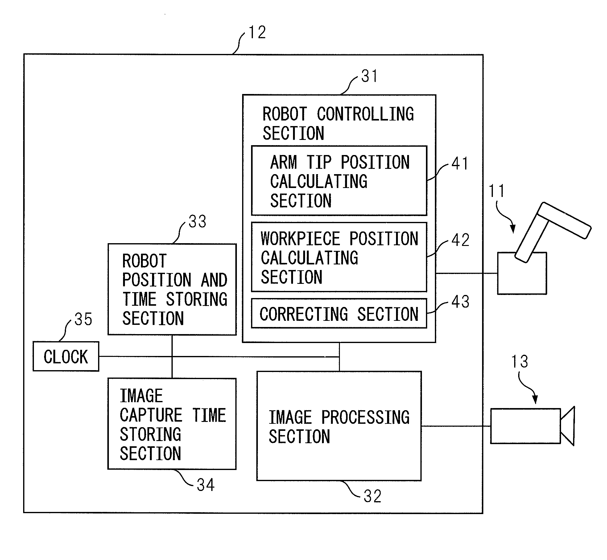
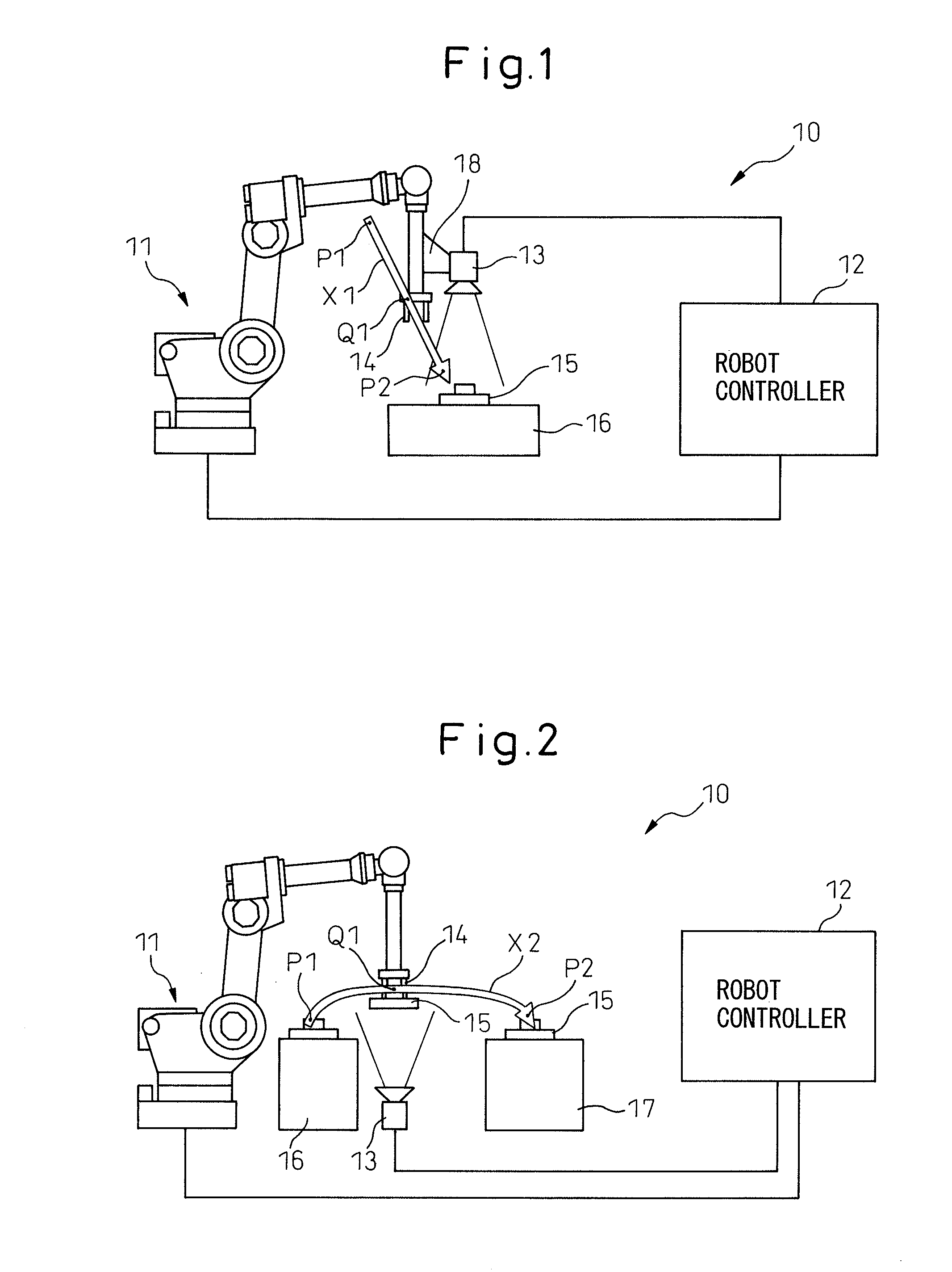
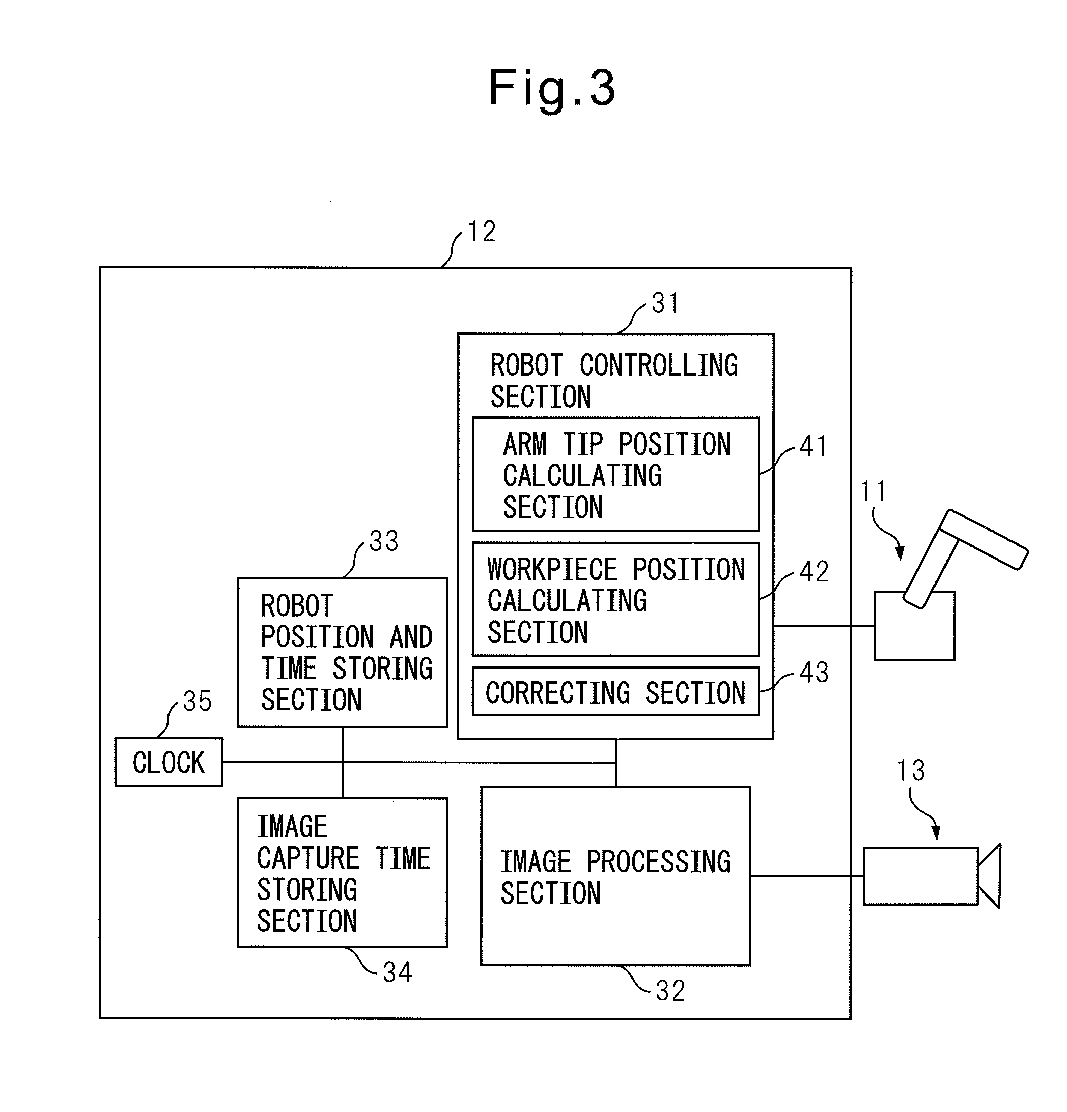
[0031]FIG. 1 is a diagram illustrating an overall configuration of a robot system in the present invention. Robot system 10 illustrated in FIG. 1 mainly includes a robot 11, and a robot controller 12 for controlling this robot 11. A hand 14 is mounted at an arm tip of robot 11 and this hand 14 grasps a workpiece 15 on a table 16. In this case, workpiece 15 mounted on table 16 is not positioned and a position of workpiece 15 is uncertain.

[0032]As illustrated in FIG. 1, a camera 13 is mounted at the arm tip of robot 11 via a bracket 18. The position W1 of workpiece 15 mounted on table 16 is measured by using camera 13 as a visual sensor. Based on the measured positional information of workpiece 15, robot 11 moves to a position where workpiece 15 is to be grasped.

[0033]Robot 11 is a well-known typical robot manipulator (hereinafter referred to as robot) and its mechanism is not limited to a particular one so long as it can reach a position and posture to perform an operation. Hand 14 a...

second embodiment

[0063]Because the position of workpiece 15 on table 16 is uncertain as described above, robot 11 may grasp workpiece 15 with a deviation. In the second embodiment, camera 13 is used for measuring the amount of the grasping deviation while workpiece 15 is being transferred.

[0064]As indicated by arrow X2 in FIG. 2, robot 11 is programmed to grasp workpiece 15 at an operation start position P1 on table 16 and move to a position P2 on table 17 via an image capture position Q1 and put workpiece 15 on table 17. As described above, a program taught to robot 11 tries to capture an image at the capture position Q1. However, in the case of delay of software and the like, the image is captured at an image capture position Q1′ a little deviated from the image capture position Q1.

[0065]In the second embodiment, in order to correct the grasping deviation of workpiece 15 by hand 14, a relative position of workpiece 15 with respect to an arm tip of robot 11 is measured. Assuming that a position of ...


PUM


Abstract

A robot system (10) includes: a processing section (32) that calculates positional information of a workpiece with respect to a visual sensor (13); a clock (35) to which a robot controlling section (31) and the processing section access to check a present time; a first storing section (33) that sequentially stores first times at a predetermined cycle in combination with positional information items of an arm tip at the first times, respectively; a second storing section (34) that stores a second time when the visual sensor measures the workpiece; an arm tip position calculating section (41) that calculates positional information of the arm tip when the visual sensor measures the workpiece based on the second time, at least two of the first times before and after the second time among the first times and the positional information items of the arm tip corresponding to the respective first times; and a workpiece position calculating section (42) that calculates positional information of the grasped workpiece with respect to the arm tip based on the positional information of the arm tip and the workpiece. Consequently, even when the workpiece is imaged without temporarily stopping operation of the robot, a position of the workpiece can be accurately calculated based on an accurate robot position.

Description

BACKGROUND OF THE INVENTION[0001]1. Field of the Invention[0002]The present invention relates to a robot system that operates a robot by using positional information of a workpiece detected by a visual sensor.[0003]2. Description of the Related Art[0004]In order to perform operations such as handling and processing of a workpiece by using a robot, a position at which the workpiece is disposed and a grasping deviation of the workpiece grasped by the robot have to be accurately recognized. For this reason, in recent years, a visual sensor is used for visually recognizing the position of the workpiece and the grasping deviation of the workpiece.[0005]When a camera is attached to a robot arm tip and the position of the workpiece disposed on a table and the like is measured, the position of the workpiece is recognized. In addition, when the position of the workpiece grasped by the robot is measured by a stationary camera, the grasping deviation is recognized.[0006]In order to calculate t...

Claims


Application Information

Patent Timeline
Patent Type & Authority Applications(United States)
IPC IPC(8): B25J13/08
CPCB25J9/1697
Inventor BAN, KAZUNORIWARASHINA, FUMIKAZUYAMADA, MAKOTONAMIKI, YUUTA
Owner FANUC LTD
Why Eureka
Try Eureka