High voltage circuit for electrical stimulation

a high-voltage circuit and electrical stimulation technology, applied in the field of modules, can solve the problems of large capacitors, inability to control the full current shape, and disallow the use of electrodes for other functions, such as battery charging, and achieve the effect of accurately controlling the shape of the stimulus current and charging capacitor 8 (c2) very quickly

Active Publication Date: 2011-09-15
NOUVEAUX ETAB CHARLES MARTIN
View PDF21 Cites 4 Cited by
  • Summary
  • Abstract
  • Description
  • Claims
  • Application Information

AI Technical Summary

Benefits of technology

[0055]It should be noted that the transformer operation at high frequency has another advantage. The primary current pulse can be filtered using a very small ceramic capacitor instead of a large tantalum capacitor as in the prior art.
[0056]In order to accurately control the shape of the stimulus current, the present invention additionally proposes to insert a high voltage cur...

Problems solved by technology

Prior art has several drawbacks:the transformer has to store the energy of each pulse.
Such capacitors are also quite large.
This solves the issue of peak current control but this does not allow...

Method used


Image

  • High voltage circuit for electrical stimulation
  • High voltage circuit for electrical stimulation
  • High voltage circuit for electrical stimulation

Examples


Embodiment Construction

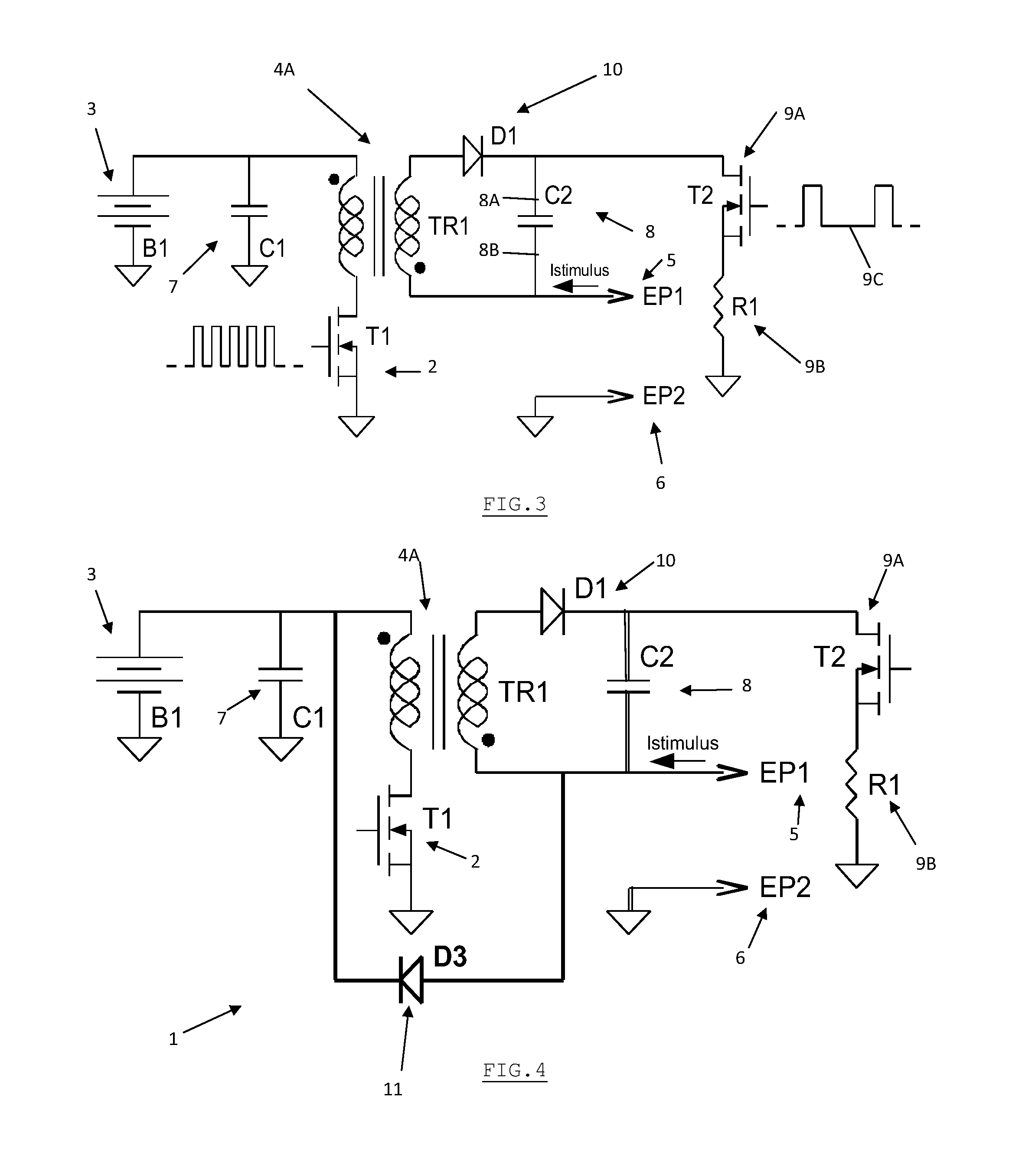
[0049]The originality of the present invention lies in the idea of storing the stimulus energy in a capacitor instead of in a transformer and in the addition of a simple high voltage current limiting circuit to control the stimulus.

[0050]The present invention allows a tight control of the current meaning that the previous invention of EP 1 968 359 A1 is still fully applicable.

[0051]Adding extra electrodes is possible and only requires a limited number of small additional components.

Principle

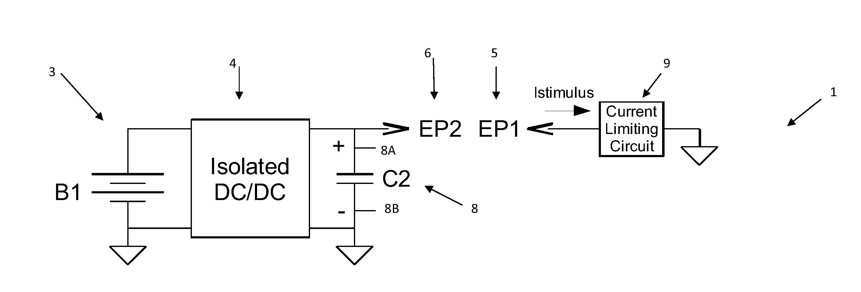
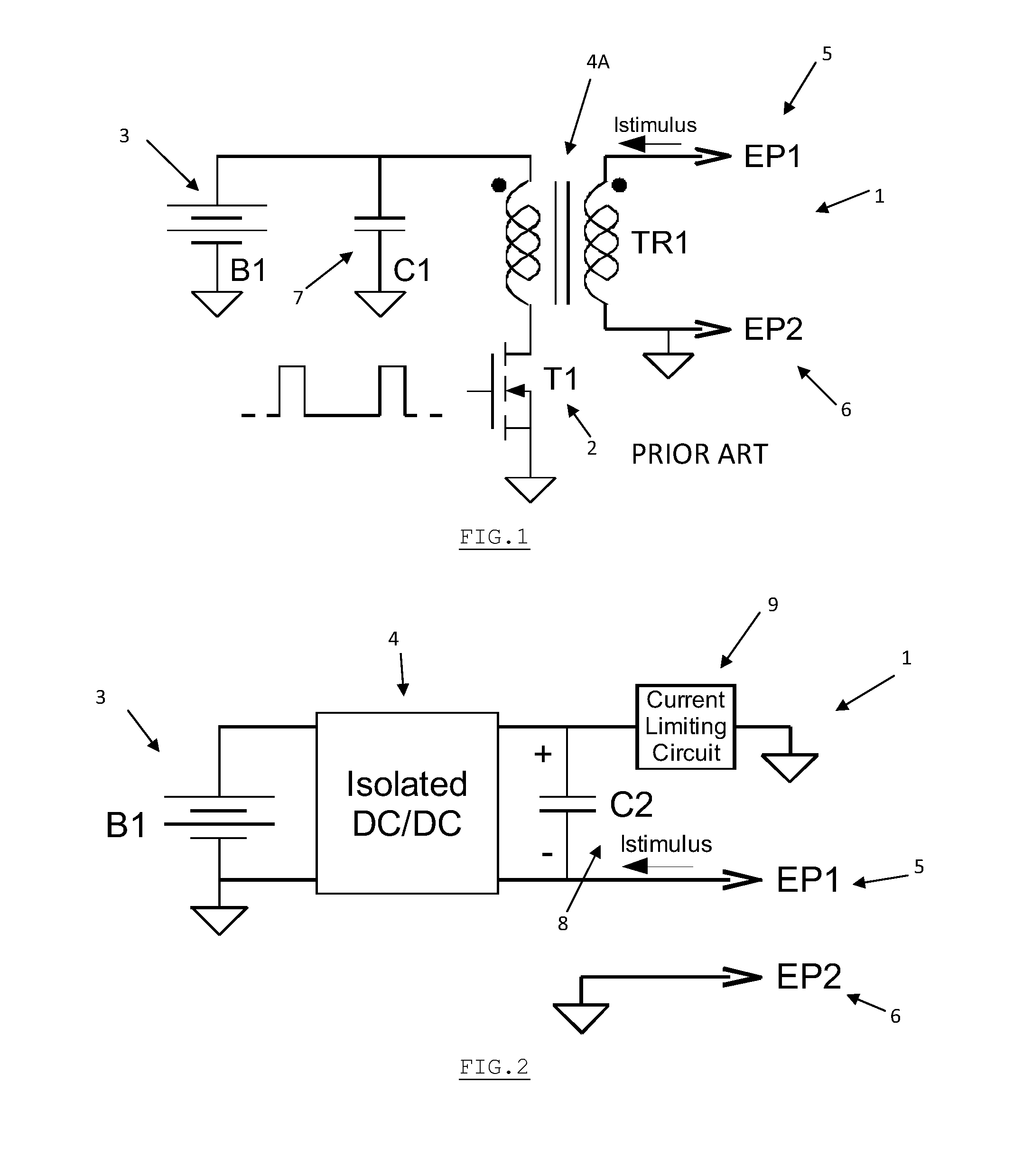
[0052]In order to reduce the size of the transformer, the present invention thus proposes to store the energy of the stimulus pulse in a capacitor 8 (called C2) instead of a transformer (see FIG. 2). For the sake of the example, a 4,7 nF / 1000V capacitor can store up to 2.35 mJ but has dimensions of only 4.5 mm×2 mm×2 mm (to be compared with 20 mm×15 mm×15 mm as above).

[0053]In order to charge this capacitor 8 to 1000V starting from the 3V battery 3, a classical isolated DC / DC converter 4 is pro...


PUM


Abstract

The present invention relates to a remote-receiving circuit (1) for providing and controlling an electric stimulus applied to an animal, the circuit (1) comprising:
    • an isolated DC/DC converter (4) having a low voltage input powered by an energy source (3) and a high voltage output connected to a storage capacitor (8) suitable to be charged with stimulus energy by said converter (4);
    • a first electrode (5) and a second electrode (6) configured to be in contact with the animal for delivering to it high voltage stimulus current and connected to the respective ends of said storage capacitor (8);
    • a current-limiting circuit (9) connected in series with the storage capacitor (8) to control the stimulus current delivered to the animal through the electrodes (5, 6).

Description

FIELD OF THE INVENTION[0001]The present invention relates to a module circuit for controlling an electric stimulus applied to an animal. The stimulus is usually generated by a means such as a collar bearing electrodes and attached to the animal's neck. The collar is typically remote-controlled by radio-frequency means. The intensity of the stimulus through the skin of the animal is preferably variable in order to train the animal.STATE OF THE ART[0002]Dog handlers often use electrical collars in order to keep control of their dog.[0003]FIG. 1 shows a typical module that generates the electrical stimulus through electrodes EP1 and EP2.[0004]The circuit 1 depicted in FIG. 1 is powered by a low voltage battery 3, typically a 3V-battery, and works in two phases:[0005]a first phase consists in charging the transformer 4A (TR1) by switching transistor 2 (T1) ON during a quite large amount of time, for example 1 ms. During this time, the current in the primary of the transformer 4A linearl...

Claims


Application Information

Patent Timeline
IPC IPC(8): A01K15/00H01T23/00
CPCA01K15/021H05C3/00H05C1/04
Inventor FREBEL, FABRICEMANGUETTE, BERNARD
Owner NOUVEAUX ETAB CHARLES MARTIN
Why Eureka
Try Eureka