Turbojet engine nacelle

Active Publication Date: 2011-09-15
SAFRAN NACELLES
View PDF11 Cites 0 Cited by
  • Summary
  • Abstract
  • Description
  • Claims
  • Application Information

AI Technical Summary

Benefits of technology

One aim of the present invention is therefore to provide a turbojet engine nacelle that can be attached on a substantially horizontal attachment pylon and having good maneuverability to easily access the inside of the nacelle downstream of the inner panel.
The outer panel of the nacelle according to the invention comprises a moving part attached to the air intake lip and extending downstream of the inner panel and therefore over at least the zone where the fan is located. The outer panel according to the invention also comprises at least one fixed part fastened to the central structure and intended to nest with the moving part. Thus, when the moving part goes from a maintenance position in which said moving part attached to the air intake lip is moved away from the fixed part(s) and the central outer cowl to an operating position where the moving part and the fixed part are nested together to ensure the aerodynamic continuity of the outside of the nacelle, the fixed part(s) make it possible to guide the moving part so as to facilitate maneuverability while preventing any jamming with elements of the nacelle according to the invention, in particular the attachment pylon. The user can therefore easily access the equipment housed in the region extending downstream of the air intake structure.
Moreover, advantageously, it is possible to group together internal equipment located inside the nacelle under at least one fixed part. As a result, in the event the moving part goes from the operating position to the maintenance position, all risks of locking and percussion between said moving part and this internal equipment are prevented. In this way, the nacelle according to the invention is suitable for being installed on an attachment pylon that is substantially horizontal relative to the body of the aircraft.
According to other features of the invention, the assembly according to the invention includes one or more of the following optional features, considered alone or according to all possible combinations:the moving part extends over at least part of the outer shroud of the secondary flow channel, which makes it possible to obtain a more substantial undercut of the moving structure formed by the air intake lip and the moving part;the central outer cowl is maintained by reinforcing elements configured to fasten said central outer cowl to the secondary flow path outer ring section, which makes it possible to reinforce the structural strength of the central structure;the reinforcing elements are substantially S- or C-shaped elements, which makes it possible to easily attach these elements to the central structure and to the secondary flow path outer ring section;a fixed part is a ramp mounted around an attachment pylon of the nacelle, which makes it possible to avoid any jamming between the moving part and the attachment pylon during opening;the ramp has a substantially triangular shape extending along the longitudinal axis of the attachment pylon whereof the angle at the apex is at least equal to 5°, which ensures mobility of the outer panel without jamming thereof at the attachment pylon.a fixed part extends in the upstream direction of the nacelle according to the invention along the longitudinal axis thereof;the nacelle according to the invention is a nacelle for an aircraft fuselage, in particular intended to be fastened to a substantially horizontal attachment pylon.

Problems solved by technology

Thus, upstream of the nacelle, there are deicing systems to prevent frost or ice from forming on the air intake lip and thereby greatly decreasing the performance of the engine.
Despite the efforts made to optimize the positioning of the hatches and allow the easiest possible access, it is sometimes necessary to reach said equipment using specific tools, such as an endoscope, which is not fully satisfactory in terms of monitoring this equipment.
Moreover, in the event it is necessary to replace part of the internal equipment, it is generally necessary to take out the entire air intake structure, which requires significant tools and causes immobilization of the propulsion assembly and therefore of the aircraft in general.
These constraints significantly reduce the integrity of the general aerodynamic line of the air intake structure, which the presence of access hatches further aggravates.
Nevertheless, the internal equipment housed downstream of the air intake structure remains difficult to access.
Nevertheless, this type of nacelle can be difficult to manipulate.
There is a significant risk of jamming, in particular between the attachment pylon and the outer panel.
Furthermore, this type of nacelle is not suitable for nacelles arranged at the fuselage of an aircraft and for which the attachment pylon is substantially horizontal relative to the body of the aircraft.

Method used


Image

  • Turbojet engine nacelle
  • Turbojet engine nacelle
  • Turbojet engine nacelle

Examples


Embodiment Construction

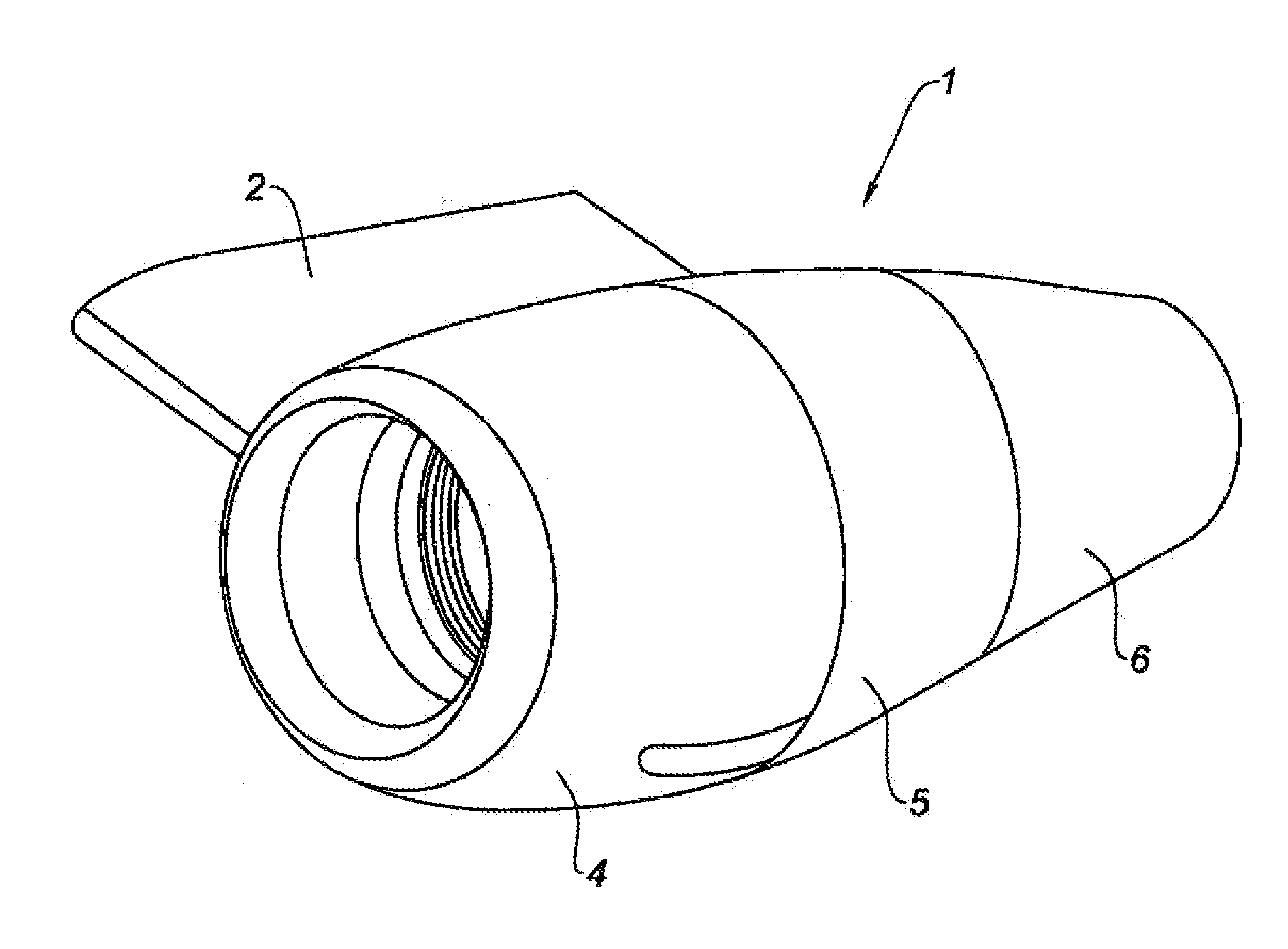
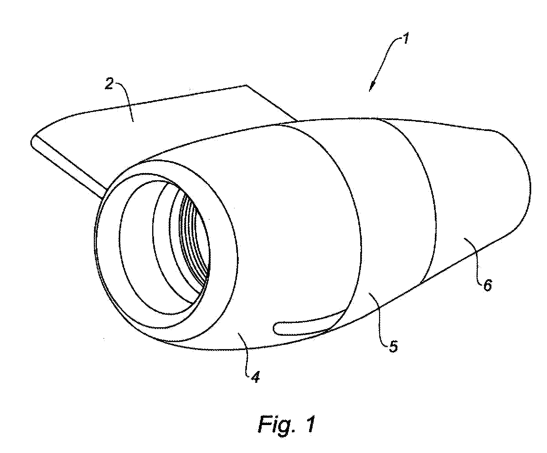
According to the embodiment shown in FIG. 1, the nacelle 1 according to the invention is intended to be attached via an attachment pylon 2 to a fixed structure of an aircraft, such as a wing. In this embodiment, the nacelle 1 according to the invention is arranged at the fuselage of the aircraft via a substantially horizontal attachment pylon relative to the body of the aircraft. The nacelle 1 according to the invention can also apply to any type of nacelle known by those skilled in the art.

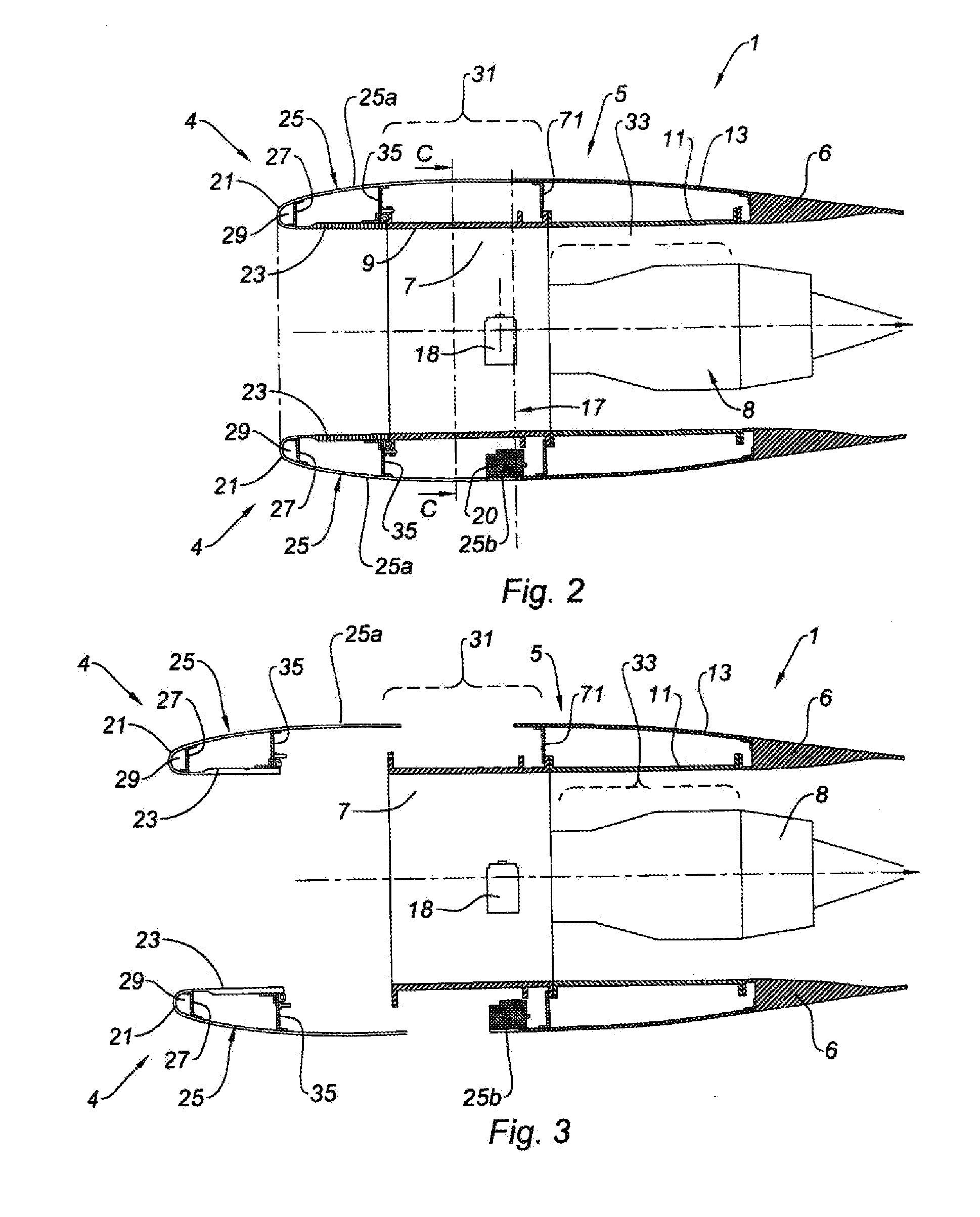
More precisely, the nacelle 1 according to the invention shown in FIG. 1 has a structure comprising an air intake structure 4 upstream, a central structure 5 surrounding a fan 7 of the turbojet engine 8 as well as a part thereof, and a downstream section 6 surrounding the downstream part of the turbojet engine 8 and generally housing a thrust reverser system (not shown).

The fan 7 of the turbojet engine is surrounded by an engine casing 9 intended to be fixed by its upstream end to the air intake ...


PUM


Abstract

The invention relates to a nacelle (1) for a turbojet engine (8) comprising: an air intake structure (4) able to channel a flow of air towards a fan (7) of the turbojet engine (8), comprising an air intake lip (21) upstream of the nacelle (1) and attached at its ends to an outer panel (25) and an inner panel (23); a central structure (5) intended to surround said fan (7) and to which the air intake structure (4) is attached in such a way as to ensure aerodynamic continuity, said central structure (5) comprising a secondary, or bypass, flow path outer ring section (11) intended to surround the engine and a central outer cowl (13), and a downstream section (6), the outer panel (25) comprising a moving part (25a) attached to the air intake lip (21) and extending downstream of the inner panel (23) and at least one fixed part (25b) fixed to the central structure (5) or to the downstream section (6) and intended to nest together with the moving part (25a) through their having complementary shapes.

Description

TECHNICAL FIELDThe invention relates to a turbojet engine nacelle.BACKGROUNDAn aircraft is propelled by one or several propulsion assemblies comprising a turbojet engine housed in a tubular nacelle. Each propulsion assembly is attached to the aircraft by an attachment pylon generally situated under a wing or at the fuselage.A nacelle generally has a structure comprising an air intake upstream of the engine, a central section intended to surround a fan of the turbojet engine, a downstream section housing thrust reverser means and intended to surround the combustion chamber of the turbojet engine.“Downstream” here refers to the direction corresponding to the direction of the air flow, in particularly of cold air, penetrating the turbojet engine. “Upstream” designates the opposite direction.The air intake comprises, on one hand, an air intake lip adapted to allow optimal collection towards the turbojet engine of the air necessary to supply the fan and the internal compressors of the tu...

Claims


Application Information

Patent Timeline
IPC IPC(8): F02C7/04
CPCB64D2033/0286B64D29/08Y10T137/0536
Inventor JORET, JEAN PHILIPPEVAUCHEL, GUY BERNARD
Owner SAFRAN NACELLES
Why Eureka
Try Eureka