
Apparatus for focusing and for storage of ions and for separation of pressure areas

Active Publication Date: 2011-09-15
CARL ZEISS MICROSCOPY GMBH
View PDF23 Cites 5 Cited by
  • Summary
  • Abstract
  • Description
  • Claims
  • Application Information

AI Technical Summary

Benefits of technology

In particular, the apparatus according to the system described herein may ensure two functions. On the one hand, the multipole alternating field may be made available such that the ions are focused radially in the area of the longitudinal axis of the through-opening. The first electrode, the second electrode, the third electrode, the fourth electrode, the fifth electrode, the sixth electrode, the seventh electrode and the eighth electrode may be connected such that a corresponding multipole alternating field, for example a quadrupole alternating field, is generated. In particular, secondary ions may be focused around the longitudinal axis of the through-opening within a small radius of, for example, in the range from 0.2 mm to 1 mm. This corresponds, for example, approximately to the radial extent of the through-opening. It is therefore then possible to use the apparatus according to the system described herein to create a transition from a first guidance system for ions, which has quite a large core radius (for example in the range from 2 mm to 50 mm) to a second guidance system with a comparatively small core radius (for example in the range from 0.1 mm to 1 mm), without ions inadvertently being reflected back into the container on the apparatus according to the system described herein, or being neutralized on the apparatus according to the system described herein. Furthermore, this prevents axial components of the kinetic energy of the ions from being converted to radial components of the kinetic energy of the ions. The apparatus according to the system described herein may be particularly suitable for use as a pressure stage.
On the other hand, the multipole unit of the apparatus according to the system described herein may be at a suitable potential (referred to in the following text as the mirror potential). This makes it possible for ions which have not yet been braked to thermal energy to be reflected back into the container from the multipole unit, such that they pass through the container once again. This once again results in impacts with the gas particles in the container, as a result of which these reflected ions may still transmit energy. The mirror potential may be switched off as soon as the ions have been brought to the thermal energy.
A further embodiment of the apparatus according to the system described herein additionally or alternatively provides for the multipole unit to be formed from at least one printed circuit board. By way of example, the printed circuit board is formed from epoxy resin or a non-conductive material, for example a ceramic or a plastic. Furthermore, the printed circuit board may be formed from a bendable and / or flexible material. The printed circuit board embodiment may be particularly advantageous because of simple manufacturing. For example, the through-opening may be produced with only a small amount of effort, for example by milling out the printed circuit board. Adjacent electrodes may be separated from one another by insulating layers and may be driven, for example by capacitive voltage dividers, such that the multiple alternating field is produced.
Analyses have shown that the embodiment of the first opening and the arrangement of multipole devices in order to provide multipole alternating fields along the axis as described above may ensure on the one hand that the ions can be focused onto a small radius around the axis, while on the other hand achieve good pressure stage characteristics.

Problems solved by technology

This once again results in impacts with the gas particles in the container, as a result of which these reflected ions may still transmit energy.

Method used


Image

  • Apparatus for focusing and for storage of ions and for separation of pressure areas
  • Apparatus for focusing and for storage of ions and for separation of pressure areas
  • Apparatus for focusing and for storage of ions and for separation of pressure areas

Examples


Embodiment Construction

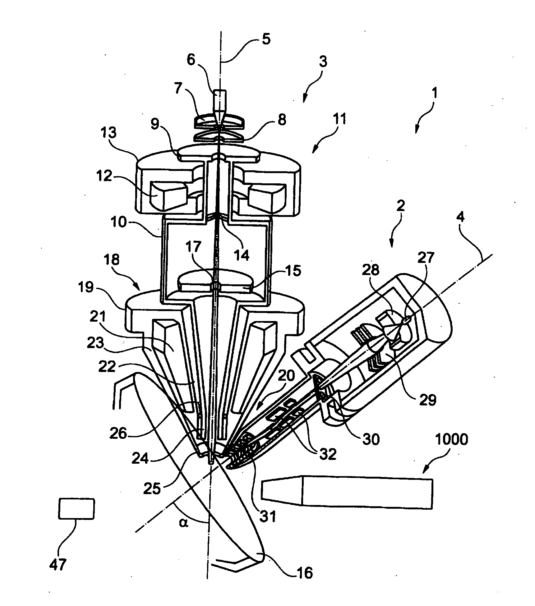
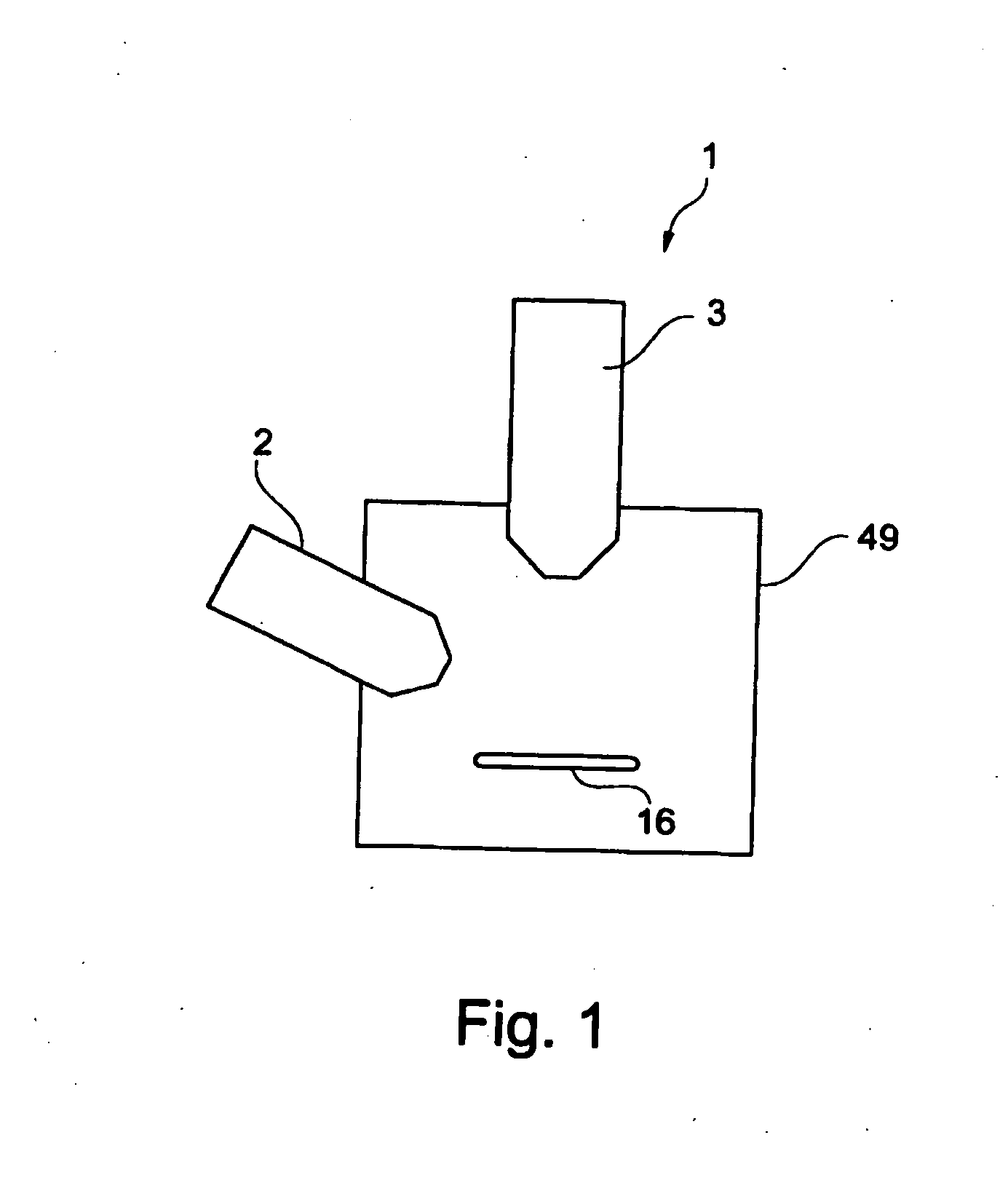
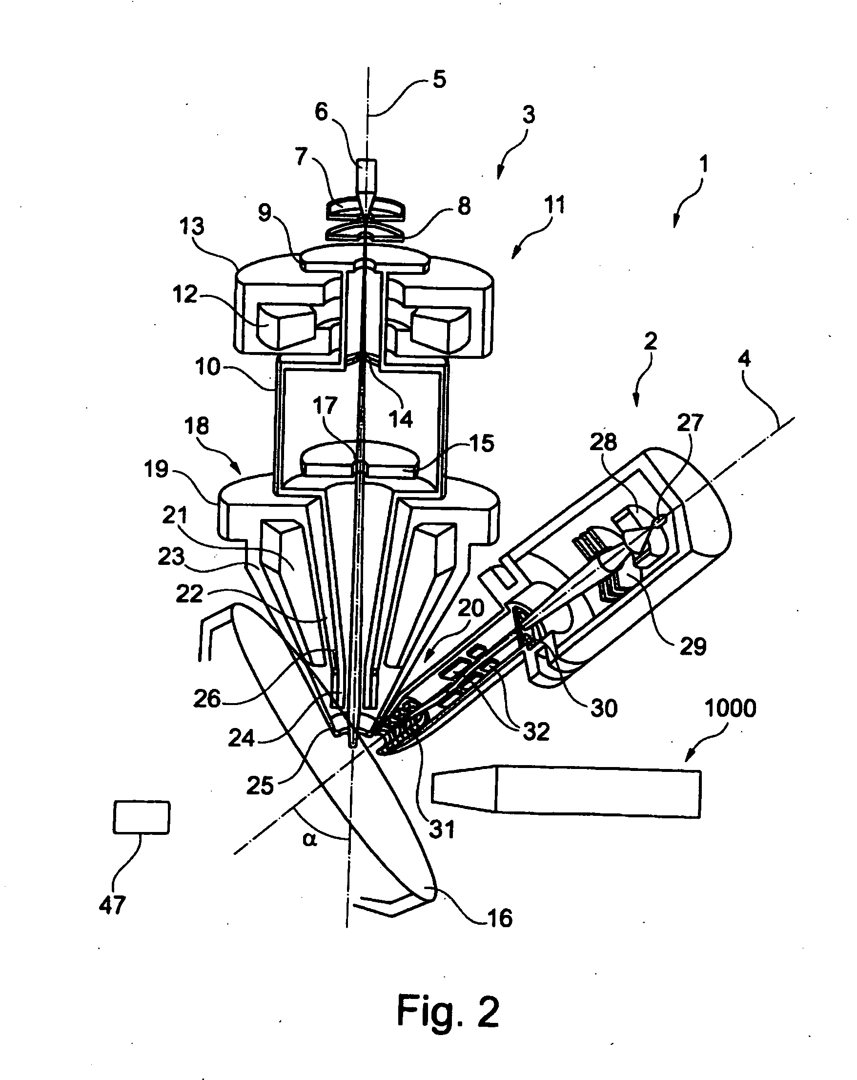
FIG. 1 shows a schematic illustration of one embodiment of a particle beam device 1 according to the system described herein. The particle beam device 1 has a first particle beam column 2 in the form of an ion beam column, and a second particle beam column 3 in the form of an electron beam column. The first particle beam column 2 and the second particle beam column 3 are arranged on a sample chamber 49, in which a sample 16 to be examined is arranged. It is explicitly noted that the system described herein is not restricted to the first particle beam column 2 being in the form of an ion beam column and the second particle beam column 3 being in the form of an electron beam column. In fact, the system described herein also provides for the first particle beam column 2 to be in the form of an electron beam column and for the second particle beam column 3 to be in the form of an ion beam column. A further embodiment of the system described herein provides for both the first particle be...


PUM


Abstract

An apparatus for focusing and for storage of ions and an apparatus for separation of a first pressure area from a second pressure area are disclosed, in particular for an analysis apparatus for ions. A particle beam device may have at least one of the abovementioned apparatuses. A container for holding ions and at least one multipole unit are provided. The multipole unit has a through-opening with a longitudinal axis as well as a multiplicity of electrodes. A first set of the electrodes is at a first radial distance from the longitudinal axis. A second set of the electrodes is in each case at a second radial distance from the longitudinal axis. The first radial distance is less than the second radial distance. Alternatively or additionally, the apparatus may have an elongated opening with a radial extent. The opening has a longitudinal extent which is greater than the radial extent.

Description

TECHNICAL FIELDThis application relates to an apparatus for focusing and for storage of ions, and to an apparatus for separation of a first pressure area from a second pressure area, in particular for an analysis apparatus for ions. This application also relates to a particle beam device having at least one of the abovementioned apparatuses.BACKGROUND OF THE INVENTIONParticle beam devices have already been in use for a very long time, in order to obtain knowledge about the characteristics and behavior of samples in specific conditions. One of these particle beam devices is an electron beam device, in particular a scanning electron microscope (also referred to in the following text as an SEM).In the case of an SEM, an electron beam (also referred to in the following text as the primary electron beam) is generated by a beam generator, and is focused by a beam guidance system, in particular an objective lens, onto a sample to be examined. The primary electron beam is passed over a surf...

Claims


Application Information

Patent Timeline
IPC IPC(8): H01J49/26H01J3/14
CPCH01J49/065H01J49/067H01J49/4235H01J49/14H01J49/4225H01J49/068
Inventor LAUE, ALEXANDERGLASMACHERS, ALBRECHTHENDRICH, CHRISTIANPREIKSZAS, DIRKALIMAN, MICHELMANTZ, HUBERTZEILE, ULRIKEDOMER, HOLGER
Owner CARL ZEISS MICROSCOPY GMBH
Learn More