
Blower type chemical diffusing apparatus with fuel cell power supply

a technology of fuel cell power supply and chemical diffusing apparatus, which is applied in the direction of liquid degasification, machine/engine, separation process, etc., can solve the problems of increasing the cost of the apparatus, affecting the efficiency of the apparatus, and limiting the cell's capacity, so as to increase the volume of the fuel tank and thin the entire apparatus.

Active Publication Date: 2011-09-15
FUMAKILLA LTD
View PDF14 Cites 7 Cited by
  • Summary
  • Abstract
  • Description
  • Claims
  • Application Information

AI Technical Summary

Benefits of technology

The apparatus provides extended operational time, reduces waste, and allows for efficient chemical diffusion and volatilization, enabling portable and continuous use without the need for water reservoirs, while promoting chemical atomization and volatilization through airflow.

Problems solved by technology

Such cells have their limits in the period of service and when the service period is expired they are replaced with unused ones while being disposed of as refuse.
For this reason, they are economically disadvantageous and also entail the problem of refuse disposal.
However, the need for such a water reservoir must raise the cost of the apparatus and increase its internal space.
These hot chemical volatilizing devices are generally large in power consumption for heating and, since they typically necessitate an AC power supply to energize the heater, the site of their use is limited to the inside of a house where the power supply is available, presenting the inconvenience that they cannot be used outdoors.
The apparatus, however, in which the number of battery cells used is more than small and their duration in service is relatively short, is not economical since they must very often be renewed.
Let alone, these cells can hardly be its power supply if the apparatus requires heating at an elevated temperature.
Here again, such cells have their limits in the period of service and when the service period is expired they are replaced with unused ones while being disposed of as in refuse, presenting the problem of refuse disposal.

Method used


Image

  • Blower type chemical diffusing apparatus with fuel cell power supply
  • Blower type chemical diffusing apparatus with fuel cell power supply
  • Blower type chemical diffusing apparatus with fuel cell power supply

Examples


Embodiment Construction

[0075]Mention is now made of a first form of implementation of the present invention.

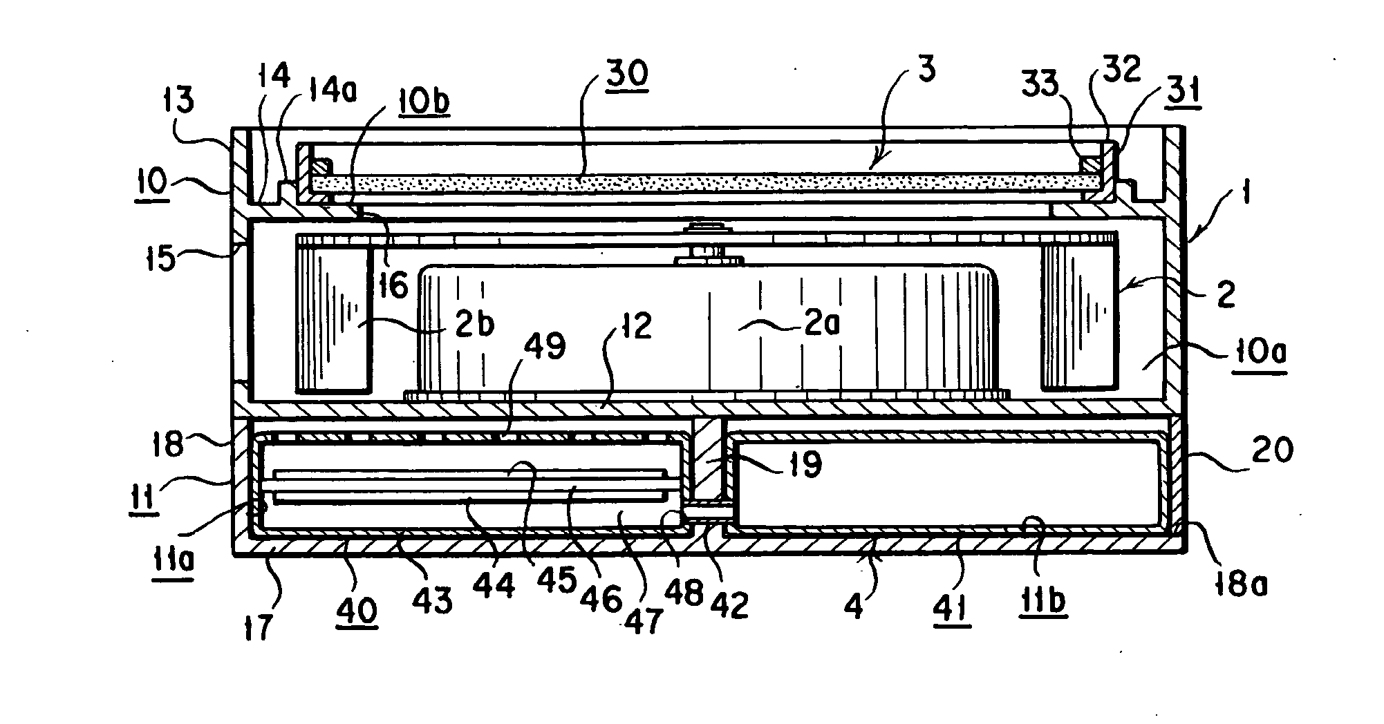
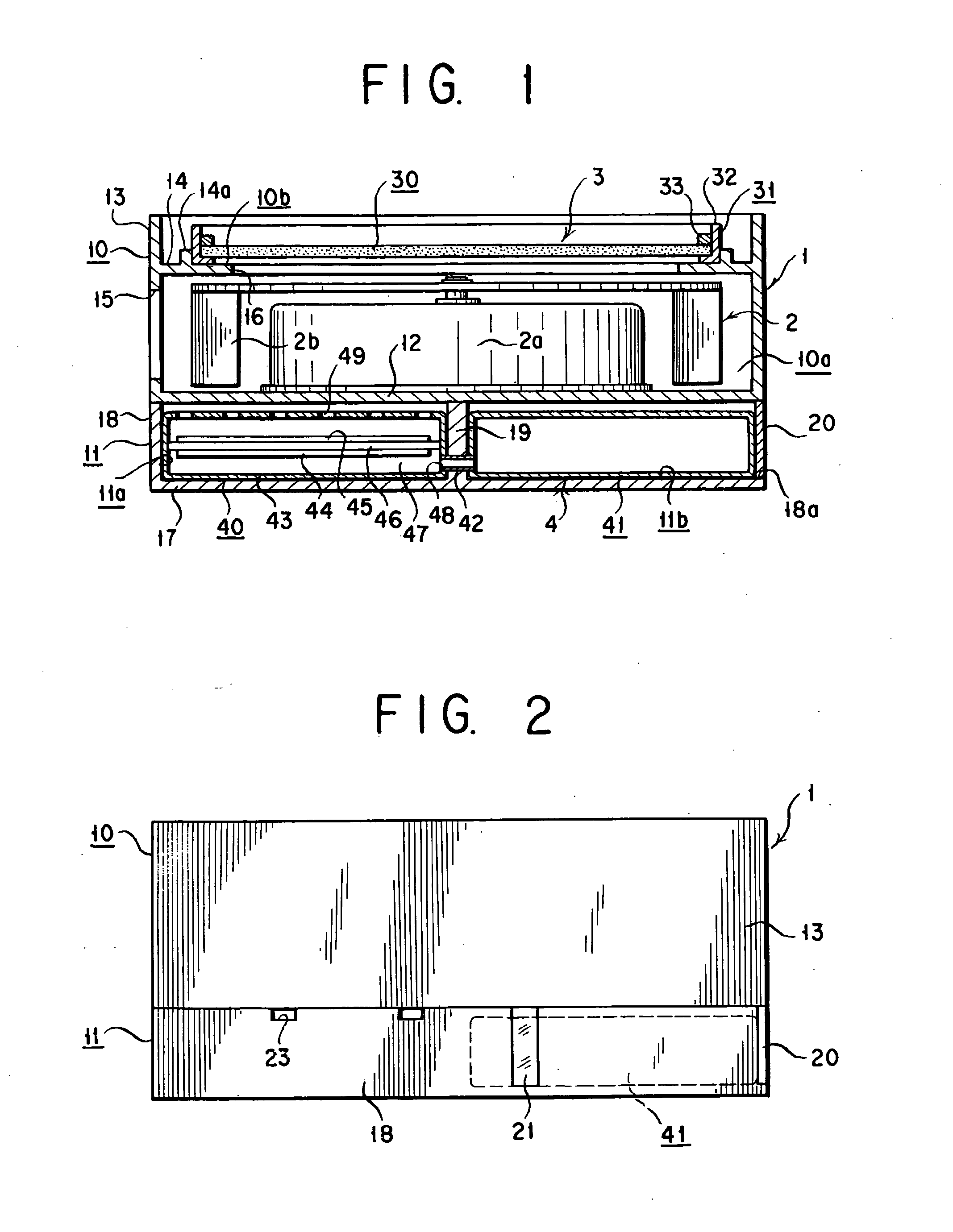
[0076]As shown in FIGS. 1 and 2, a blower type chemical diffusing apparatus of this form of implementation comprises an apparatus body 1 and an air blower 2, a chemical retainer 3 and a fuel cell 4 which are included in the apparatus body 1. The apparatus operates with the air blower 1 driven to generate a wind, which is passed through the chemical retainer 3 to emit chemical therein into an atmosphere.

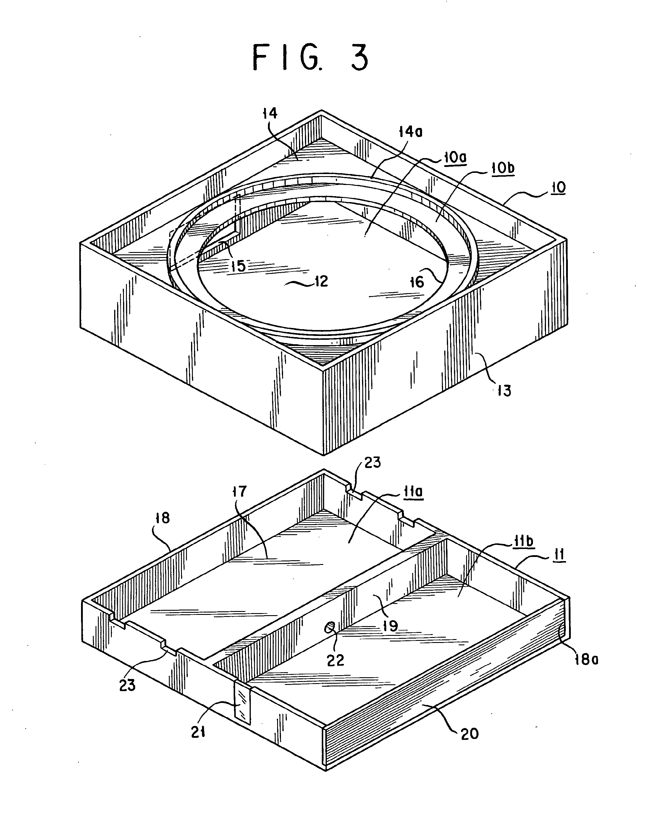
[0077]The apparatus body 1 comprises a main frame 10 and a fuel cell mounting frame 11. The main frame 10 has the air blower 2 and the chemical retainer 3 mounted therein while the fuel cell mounting frame 11 has the fuel cell 4 accommodated therein.

[0078]The fuel cell mounting frame 11 is detachably mounted to the main frame 10.

[0079]Separating the apparatus body 1 into the main frame 10 and the fuel cell mounting frame 11 in this way allows separating an operation in which the apparatus body 1 is lo...


PUM

PropertyMeasurementUnit
temperatureaaaaaaaaaa
timeaaaaaaaaaa

Abstract

A blower type chemical diffusing apparatus is disclosed which can be of service for an extended period of time and does not give rise to refuse disposal problems. The blower type chemical diffusing apparatus of the invention has an air blower, a chemical retainer and a fuel cell included in the apparatus body whereby powering the air blower to drive it with the fuel cell causes chemical from the chemical retainer to be emitted into an environmental atmosphere.

Description

[0001]This application is a Continuation of U.S. application Ser. No. 11 / 632,099 filed Jan. 10, 2007, which application is a U.S. National Phase Application of International Application PCT / JP2005 / 013521 filed Jul. 15, 2005, the entire contents of both of which are incorporated herein by reference.TECHNICAL FIELD[0002]The present invention relates to a blower type chemical diffusing apparatus for volatilizing and diffusing a chemical such as an aromatic, deodorant, germicide, miticide, vermin or pest repellent, insecticide, or vermin growth retardant or sucking inhibitor, by the force of an airflow or wind generated by an air blower. More particularly, the invention relates to such a blower type chemical diffusing apparatus in which a power supply for driving a motor in the air flower is constituted with a fuel cell.BACKGROUND ART[0003]There is known a blower type chemical diffusing apparatus as disclosed in JP 2002-291392 A.[0004]Such a blower type chemical diffusing apparatus is p...

Claims


Application Information

Patent Timeline
Patent Type & Authority Applications(United States)
IPC IPC(8): B01F3/04
CPCA01M1/2033A01M1/205A61L9/122Y02B90/14A61L2209/132A61L2209/22H01M2250/10A61L9/145Y02B90/10Y02E60/50A01M1/20A01M1/22A01M13/00
Inventor YAMASAKI, SATOSHIYAMAMOTO, KAZUNORIKAWAMURA, SHINYATAKEI, YASUHARUJO, TAKAO
Owner FUMAKILLA LTD
Learn More