Electromagnetic linear stepper motor

a linear stepper motor and electric motor technology, applied in the direction of electric controllers, dynamo-electric converter control, instruments, etc., can solve the problems of complex drive structure, inability to adjust the focal length of the lens, rigid system and limited optical quality, etc., to achieve high positioning accuracy, low energy consumption, and high rigidity

Active Publication Date: 2011-09-15
KARL STORZ GMBH & CO KG
View PDF15 Cites 5 Cited by
  • Summary
  • Abstract
  • Description
  • Claims
  • Application Information

AI Technical Summary

Benefits of technology

[0008]The embodiments are based on the object of providing a linear motor having such small dimensions that it can be inserted into endoscopes. Furthermore, the linear motor should enable a defined positioning without additional position sensors. In addition, the linear motor should exhibit large driving forces with small mass and thereby render possible a rapid, continuous and exact positioning of optical components in the largest possible range. At the same time, the beam path through the optical components must not be blocked during displacement of the components. The power loss of the linear motor should be low so that little heat is produced in the tip of an endoscope. The drive should be composed of as few as possible and as geometrically simple as possible individual components for simple manufacture and assembly.

Problems solved by technology

As a result of the rod lenses, the system is rigid and limited in optical quality.
An adjustment of the focal length of the lens is not possible.
The complex structure of the drive can be readily implemented in video cameras having lens diameters in the centimeter range but is not scalable to the size required for endoscope applications in the millimeter range.
An expensive controlling circuit is required to produce the moving field.

Method used


Image

  • Electromagnetic linear stepper motor
  • Electromagnetic linear stepper motor
  • Electromagnetic linear stepper motor

Examples


Embodiment Construction

[0047]While the invention is susceptible to various modifications and alternative forms, specific embodiments thereof are shown by way of example in the drawings and will herein be described in detail. It should be understood, however, that the drawings and detailed description thereto are not intended to limit the invention to the particular form disclosed, but on the contrary, the intention is to cover all modifications, equivalents and alternatives falling within the spirit and scope of the present invention as defined by the appended claims.

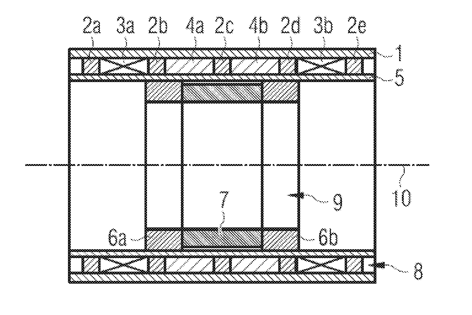
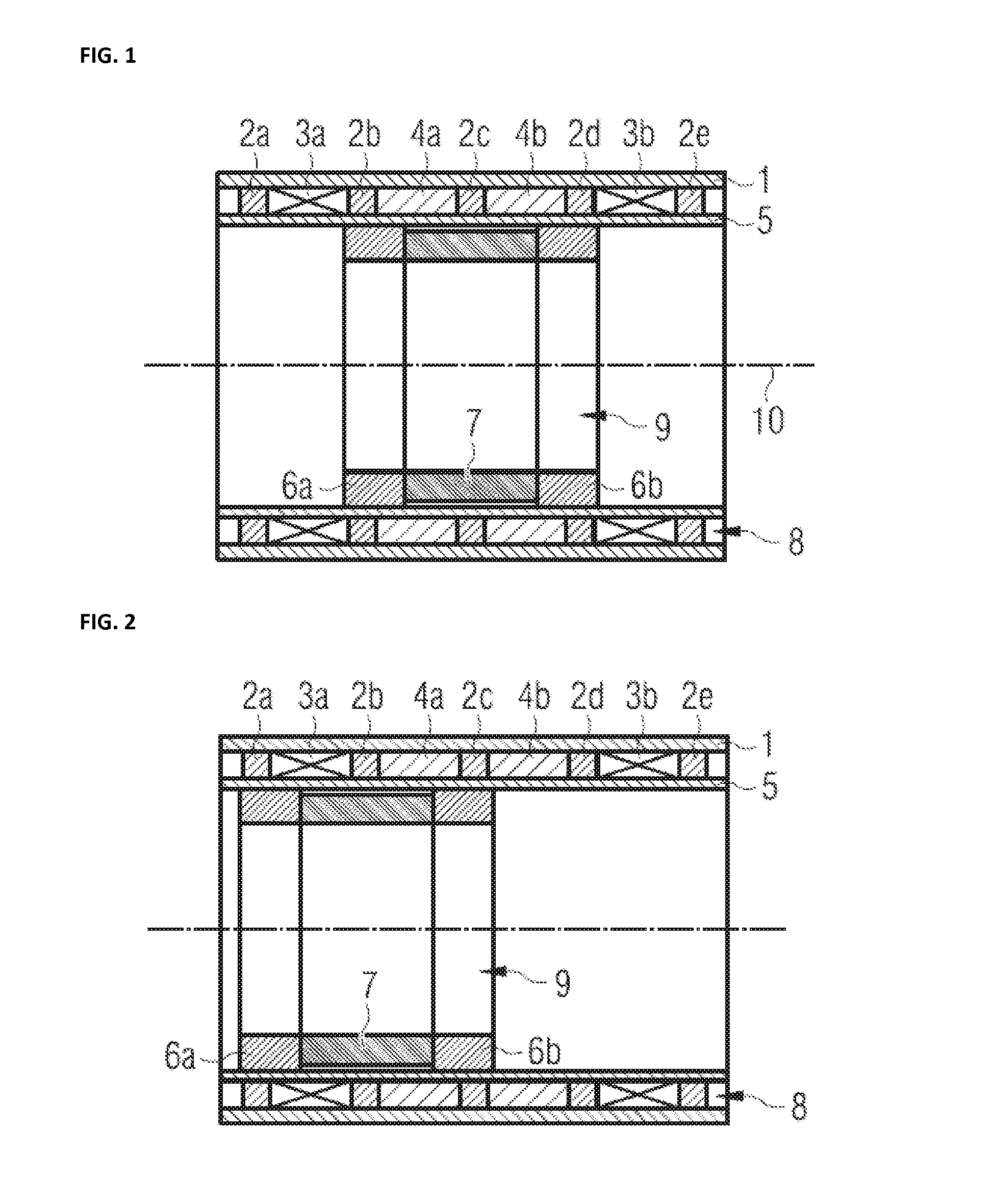
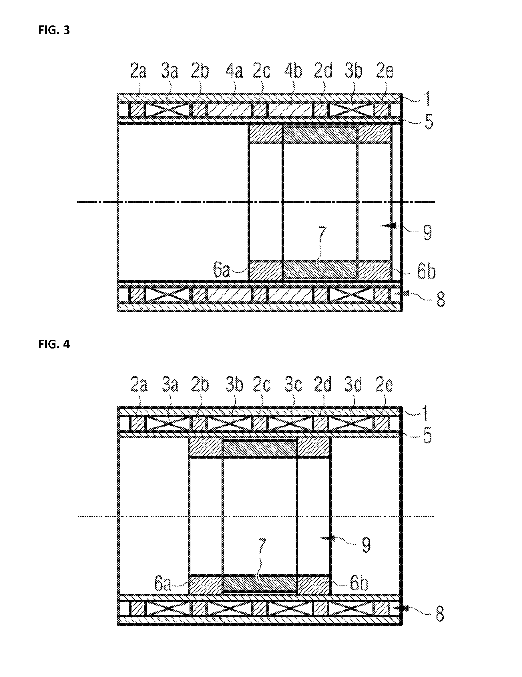
[0048]FIG. 1 shows schematically a sectional view of an exemplary embodiment in cylindrical design for N=3 stable positions. The stator 1 includes a magnetic guiding element 1 in the form of a soft-magnetic guiding tube, the (N+2)=5 stator pole pieces 2a-2e made of soft-magnetic material being disposed in the bore whereof at fixed uniform distances. The coils 3a, 3b and the non-magnetic spacers 4a, 4b are located between the stator pole piece...


PUM


Abstract

A linear stepper motor is used for the displacement of an armature parallel to a stator having N steps. The stator includes (N+2) stator pole pieces which are enclosed by a magnetic guiding element and are each approximately the same distance from neighboring stator pole pieces. Furthermore, at least one coil is located between two stator pole pieces. The armature is enclosed by the stator in the radial direction and has a permanent magnet magnetized parallel to the stator which is disposed between two armature pole pieces. As a result of the reluctance forces, the armature occupies stable idle positions inside the stator in which the stator pole pieces lie opposite the armature pole pieces. By energizing the coils with a short current pulse, the armature can be displaced inside the stator between the different stable idle positions.

Description

CROSS-REFERENCE TO RELATED APPLICATIONS[0001]The present application claims priority of German patent application No. 10 2010 015 905.0 filed on Mar. 10, 2010, the content of which is incorporated herein by reference.FIELD OF THE INVENTION[0002]The invention relates to a linear stepper motor in particular for optical systems. Such optical systems are used, for example, in endoscopes. In modern video endoscopes a camera chip and an appurtenant lens system are integrated in the endoscope tip. A miniaturized motor is required to adjust the focal length or the focus of the lens system.BACKGROUND OF THE INVENTION[0003]Classical endoscopes such as can be used, for example, for minimally invasive surgery, guide the image by means of rod lenses from the intracorporeal objective to the extracorporeal eyepiece. As a result of the rod lenses, the system is rigid and limited in optical quality. Modern video endoscopes use a camera chip in the endoscope tip. Such an endoscope is disclosed in U.S...

Claims


Application Information

Patent Timeline
Patent Type & Authority Applications(United States)
IPC IPC(8): H02K41/03H02P1/04G05B11/01
CPCH02K1/2713H02K7/08H02P8/005H02K41/031H02K41/0356H02K7/14
Inventor KELP, MARTIN
Owner KARL STORZ GMBH & CO KG
Why Eureka
Try Eureka