Testable integrated circuit and test method therefor

a technology of integrated circuits and test methods, applied in logic circuits, pulse automatic control, instruments, etc., can solve the problems of complex ics, unacceptably high overall power consumption of ics, and inability to know the overall design

Active Publication Date: 2011-09-15
III HLDG 6
View PDF8 Cites 34 Cited by
  • Summary
  • Abstract
  • Description
  • Claims
  • Application Information

AI Technical Summary

Benefits of technology

[0033]According to yet another aspect of the present invention, a method of testing an integrated circuit of the present invention is provided, comprising: selecting one of the cores for testing; bringing the wrapper of the selected core in a test mode, providing the core with a test stimulus via said wrapper, capturing the response of the c

Problems solved by technology

In fact, the complexity of such ICs has become such that distributed design approaches have been developed in which functional blocks have been defined as building blocks of the IC, with the IC being designed by the selection of predefined functional blocks.
A problem associated with complex ICs such as SoCs is that due to the high number of power-consuming semiconductor devices in the circuit, the overall power consumption of the IC may be unacceptably high, for

Method used


Image

  • Testable integrated circuit and test method therefor
  • Testable integrated circuit and test method therefor
  • Testable integrated circuit and test method therefor

Examples


Embodiment Construction

[0034]Embodiments of the invention are described in more detail and by way of non-limiting examples with reference to the accompanying drawings, wherein:

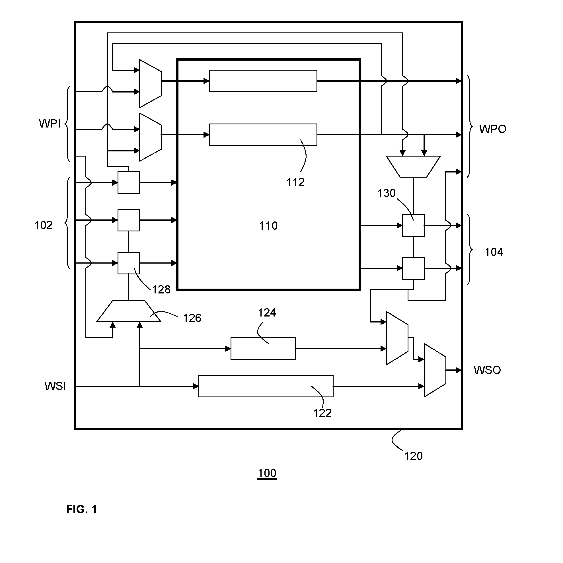
[0035]FIG. 1 schematically depicts a wrapped core of an integrated circuit;

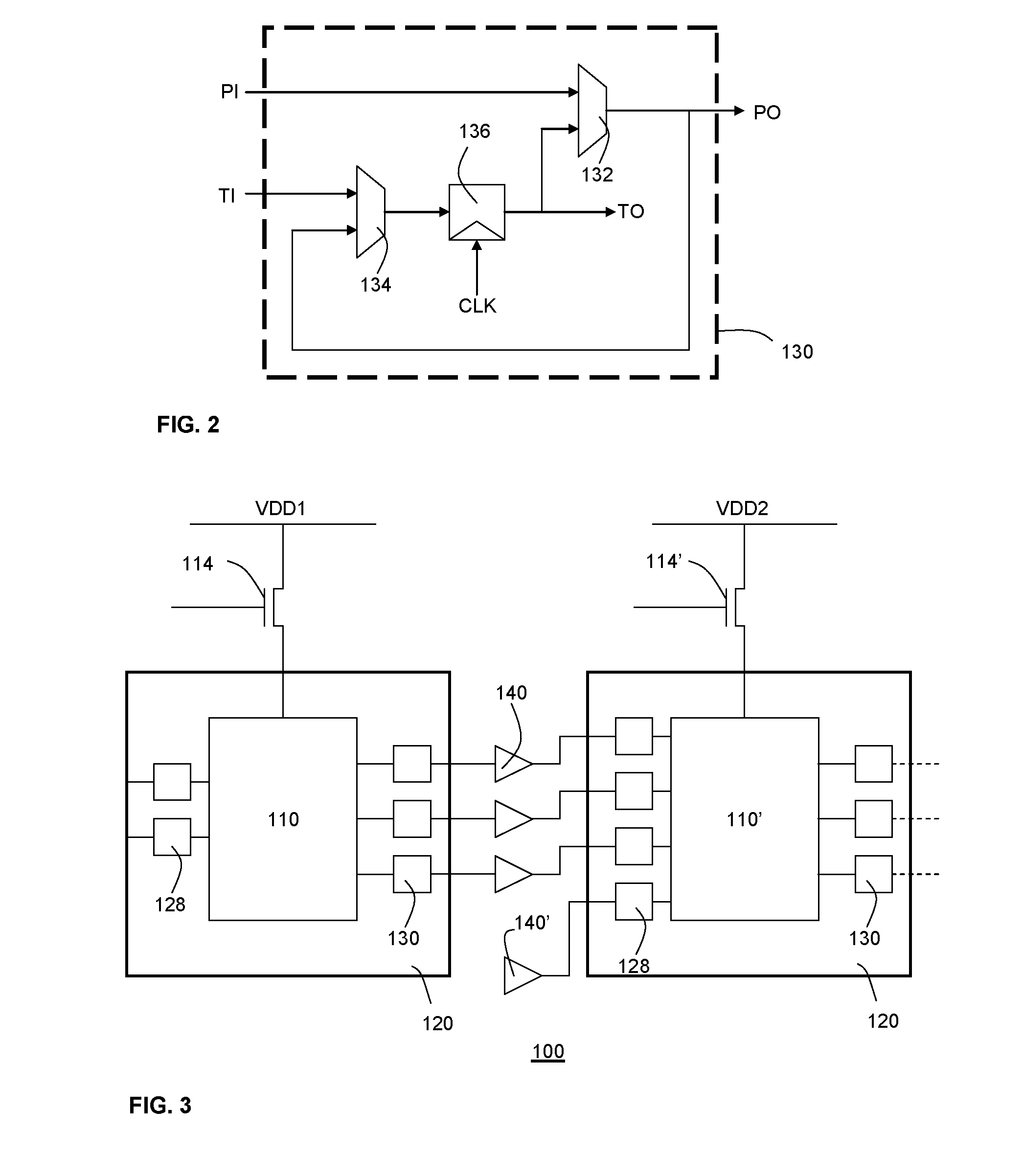
[0036]FIG. 2 schematically depicts a known wrapper isolation cell;

[0037]FIG. 3 schematically depicts a known multi-power domain IC architecture;

[0038]FIG. 4 schematically depicts a multi-power domain IC architecture in accordance with an embodiment of the present invention;

[0039]FIG. 5 schematically depicts a wrapper isolation cell in accordance with an embodiment of the present invention;

[0040]FIG. 6 schematically depicts a multiplexer for use in a wrapper isolation cell in accordance with an embodiment of the present invention;

[0041]FIG. 7 schematically depicts a wrapper isolation cell in accordance with another embodiment of the present invention;

[0042]FIG. 8 shows a comparison of the performance of ICs having different types of wrapper cells; and

[0043]FIG...


PUM


Abstract

Disclosed is an integrated circuit (200) comprising a plurality of cores (110, 110), at least some of the cores being located in different power domains (VDD1, VDD2), each core being surrounded by a test wrapper (220) comprising a plurality of wrapper cells (128, 230), wherein each of said test wrappers are located in a single power domain (VDD3) and each plurality of wrapper cells comprises wrapper output cells (230) each arranged to output a signal from its associated core, each of said wrapper output cells comprising an output level shifter (232, 240) for shifting the voltage of said signal to the voltage of the single power domain (VDD3). A method for testing such an IC and standard library cells for designing such an IC are also disclosed.

Description

FIELD OF THE INVENTION[0001]The present invention relates to an integrated circuit comprising a plurality of cores, at least some of the cores being located in different power domains, each core being surrounded by a test wrapper comprising a plurality of wrapper cells.[0002]The present invention further relates to a method of testing such an integrated circuit.BACKGROUND OF THE INVENTION[0003]Nowadays, integrated circuits (ICs) are capable of performing multiple functions, as facilitated by the ability to integrate millions of semiconductor devices such as transistors, resistors and the like onto a substrate. In fact, the complexity of such ICs has become such that distributed design approaches have been developed in which functional blocks have been defined as building blocks of the IC, with the IC being designed by the selection of predefined functional blocks. An example of such a design strategy is the System-on-Chip (SoC) approach, where multiple functional blocks, also referr...

Claims


Application Information

Patent Timeline
IPC IPC(8): H03L5/00
CPCG01R31/318508
Inventor MEIJER, RINZE IDA MECHTILDIS PETERELVIRA VILLAGRA, LUIS
Owner III HLDG 6
Why Eureka
Try Eureka