
Authenticating device with wireless directional radiation

a wireless directional radiation and authentication device technology, applied in the direction of testing/monitoring control systems, program control, instruments, etc., can solve the problems of inadvertent or deliberately gaining access to the wrong computing device by token holders, wireless transactions may radiate from the antenna of the token and propagate in an unintended direction, and the token holder may inadvertently or deliberately gain access to the wrong computing devi

Inactive Publication Date: 2011-09-15
KOZLAY DOUGLAS
View PDF22 Cites 9 Cited by
  • Summary
  • Abstract
  • Description
  • Claims
  • Application Information

AI Technical Summary

Benefits of technology

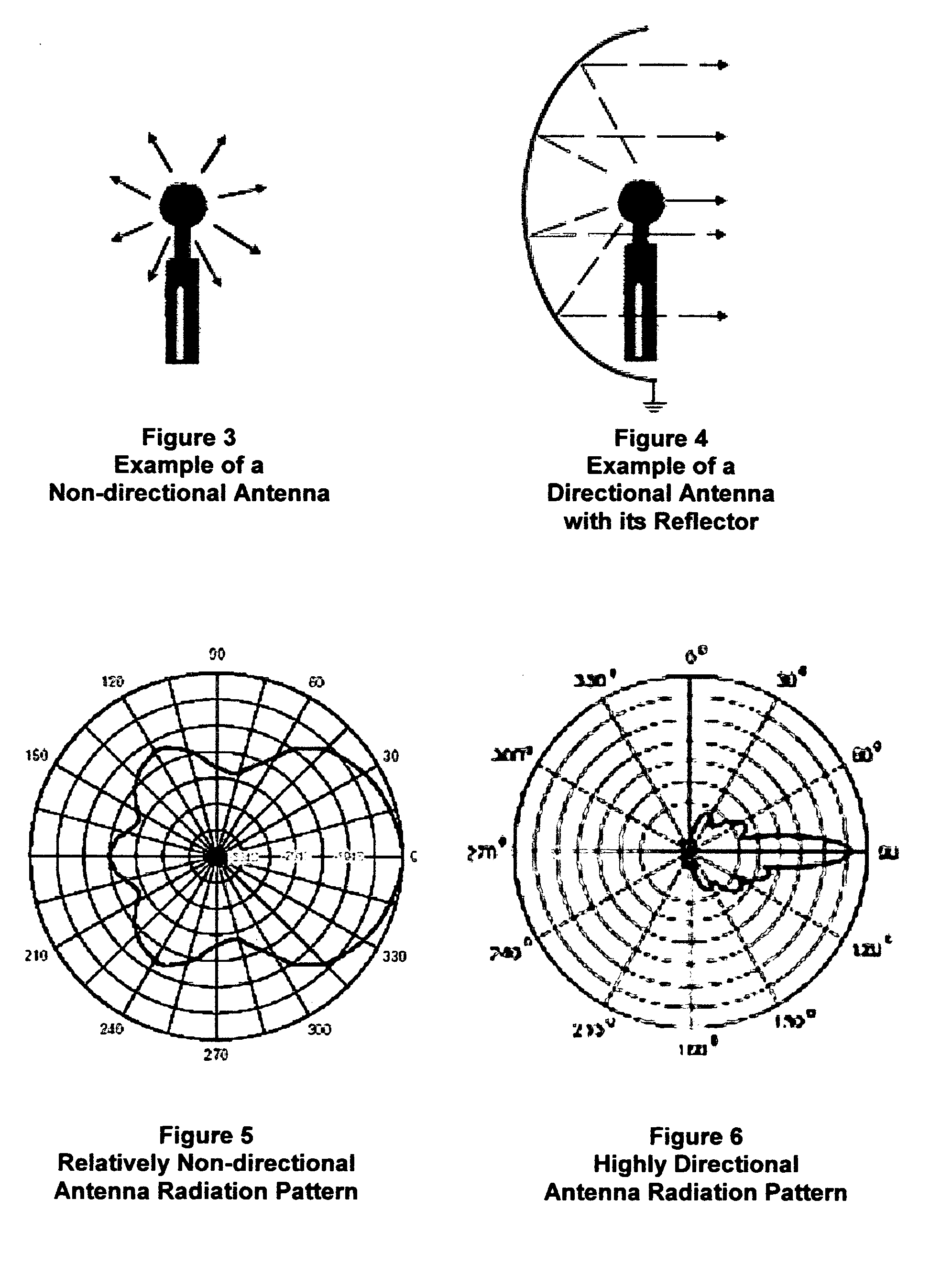
[0014]Accordingly, it is one primary object of the present invention to provide a wireless directional, user-authenticating “electronic token” that can be deliberately pointed only in the direction of (i.e., “aimed” at) intended receiver(s). Due to its' highly directional antenna radiation propagation pattern (given its' narrow-lobed, focused signal energy) the wireless user-authenticating token of the present invention, transmits little or no usable signal to unintended receivers, thereby increasing security and accuracy, while decreasing risks of unintended transmissions.
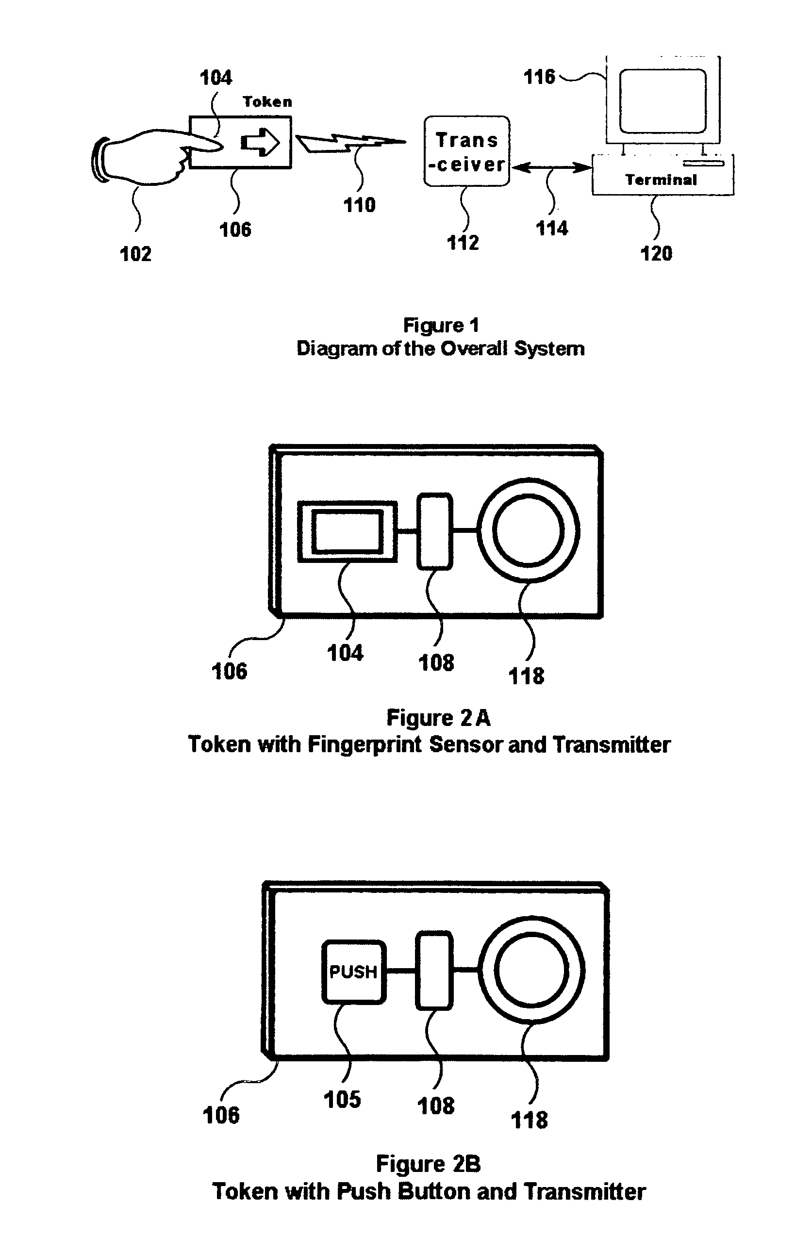
[0015]It is another primary object, to provide one or more token-aiming indicators and / or indicia upon the exterior of the token of the present invention (e.g., at least one of an arrow, a pointer, or other distinctive visual indicia such as a LED or a focused light beam) to help a user optimally “aim” and orient the token accurately only upon intended receiver or transceiver. The token-aiming indicator(s) tell the user, the most effective directional orientation of the token, thereby maximizing optimum intended transmission characteristics, while minimizing signal transmission to unintended receivers and transceivers. The benefits of this feature are that it enables users to more quickly and accurately aim their token properly; this feature also reduces frustration due to inaccurate pointing and failure to transmit and receive properly, and / or due to inadvertent communication with an unintended receiver.
[0016]It is another related object, to optionally provide a token-aiming “illuminator” (i.e., a “target designator”) to guide a user to optimally orient and aim the electronic token apparatus (essentially directly) at the intended receiver, along the path and plane of the token's maximum signal strength.
[0019]Preferably, the token also provides one or more “token aiming” indicators—e.g., visual markings, and / or LEDs which flash when pointed in the direction of detected received carrier from an intended receiver, and / or other indicia or indicators—to help the user optimally aim and orient the token. When referring to such indicia, the user will always know how to approximately best aim the token toward the intended receiver.
[0020]The tokens of the present invention may optionally also employ an “illuminating beam” to help the user better aim the token in the direction of maximum antenna output (signal strength) propagation toward an intended receiver.

Problems solved by technology

As technology improves, the transmission range of personal identifying tokens such as contactless cards and RFID tags has grown from a few centimeters to more than one meter or greater, creating a hazard that a wireless transaction may radiate from the token's antenna and propagate in an unintended direction.
Such “misdirection” could result, e.g., in an erroneous transaction at another legitimate transceiver.
Or, e.g., the misdirection could result in a false or unintended transaction with a “rogue transceiver”, which amounts to theft or worse.
Additionally, in access control applications, the token holder may inadvertently or deliberately gain access to a wrong computing device (e.g., because the wireless signal was sent in many or all directions).

Method used


Image

  • Authenticating device with wireless directional radiation
  • Authenticating device with wireless directional radiation
  • Authenticating device with wireless directional radiation

Examples


Embodiment Construction

[0048]There are many possible versions of the present invention, depending on application needs and configurations implemented.

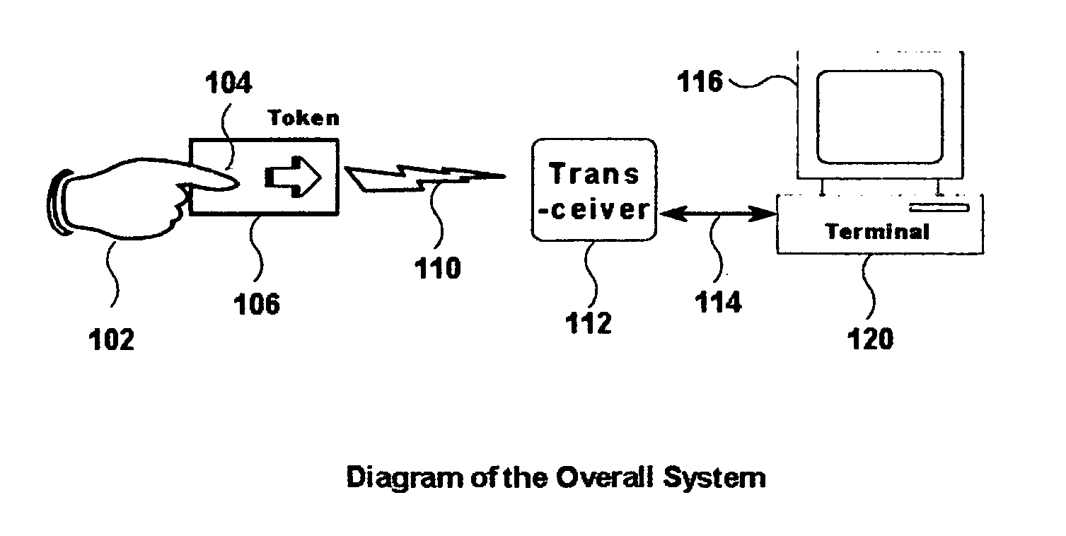
[0049]One version of the present invention can be activated only upon, and in response to a signal generated by a token transceiver.

[0050]Another version of the present invention can be activated only after successful completion of biometric authentication of a prospective user fingerprint on the electronic token, after the user presents their finger and the fingerprint sensor processor matches the inputted fingerprint in storage and determines the inputted fingerprint to represent the presence of an authorized and pre-enrolled user.

[0051]Yet another version of the present invention can be implemented with an actuator (e.g., a push-type button, or a switch) on the electronic token; in such a case, other security techniques can be used external to the electronic token to verify that the user is who they claim to be (not subjects of this application). The swit...


PUM


Abstract

A directional, wireless, user-authenticating electronic token is disclosed. The token is embedded as an integrated system (generally, within a protective electronic enclosure). Typically the present invention includes a fingerprint sensor, a processor, a power source, a token transceiver and antenna, and orientation indicia. The antenna propagates highly directional signals. This allows users to orient (i.e., “aim”) token signals toward intended transceivers (POS machines, doors, computers, etc.), while reducing risks of transacting with “unintended” transceivers outside the aimed beam. The present invention offers an improved design for electronic wireless hardware tokens: providing versatile, secure, directional, wireless, user-authenticating devices (e.g., advanced ID cards, smartcards, hybrid cards, dongles, etc.). Such devices reduce risk of unintended emissions (i.e., signals radiating in the direction of unintended transceivers). As an optional aid to pointing the device in the direction of an intended transceiver, a narrow guiding light beam can be included as a target designator.

Description

BACKGROUND[0001]1. Field of the Invention[0002]The field of the invention is wireless devices and wireless user-authenticating devices, more particularly, authenticating devices with highly directional signals and highly directional signal output lobes (footprints) for optimizing wireless message transmission in the direction of intended receivers only.[0003]2. Related Art[0004]There are a variety of “authenticating devices” in the art. Notwithstanding, the inventor has not found any other wireless authenticating devices with highly directional antenna footprints and other features and benefits of the present invention, comparable to the present invention.[0005]There are a variety of “hardware tokens” are known in the art. Typically, hardware tokens use a reduced size form factor physical enclosure, such as a USB dongle, a smartcard or other card, calculator size tokens, etc. Examples of radio frequency “hardware tokens” are products currently made and / or sold by HID; Exxon-Mobil SP...

Claims


Application Information

Patent Timeline
Patent Type & Authority Applications(United States)
IPC IPC(8): G06F7/04
CPCG06F21/35H04W12/06H04L63/0853H04L63/0492H04W12/062H04W12/068
Inventor KOZLAY, DOUGLAS
Owner KOZLAY DOUGLAS
Learn More