Piezoelectric element, liquid ejecting head, and liquid ejecting apparatus
a piezoelectric element and liquid ejecting head technology, applied in the direction of electrical equipment, device material selection, printing, etc., can solve the problems of insufficient durability, liquid ejecting head, piezoelectric element used in other apparatuses, and relatively high dielectric loss of knn materials, etc., to achieve high dielectric constant, superior durability, and high thermal stability
- Summary
- Abstract
- Description
- Claims
- Application Information
AI Technical Summary
Benefits of technology
Problems solved by technology
Method used
Image
Examples
first embodiment
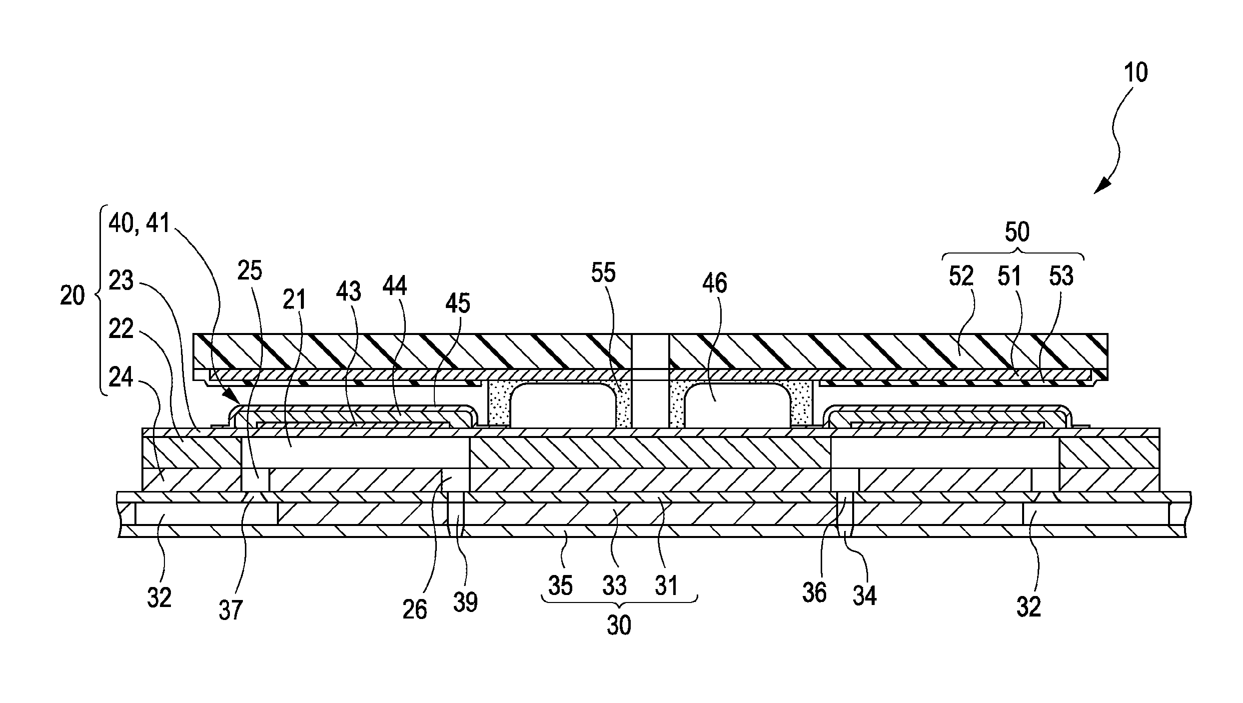
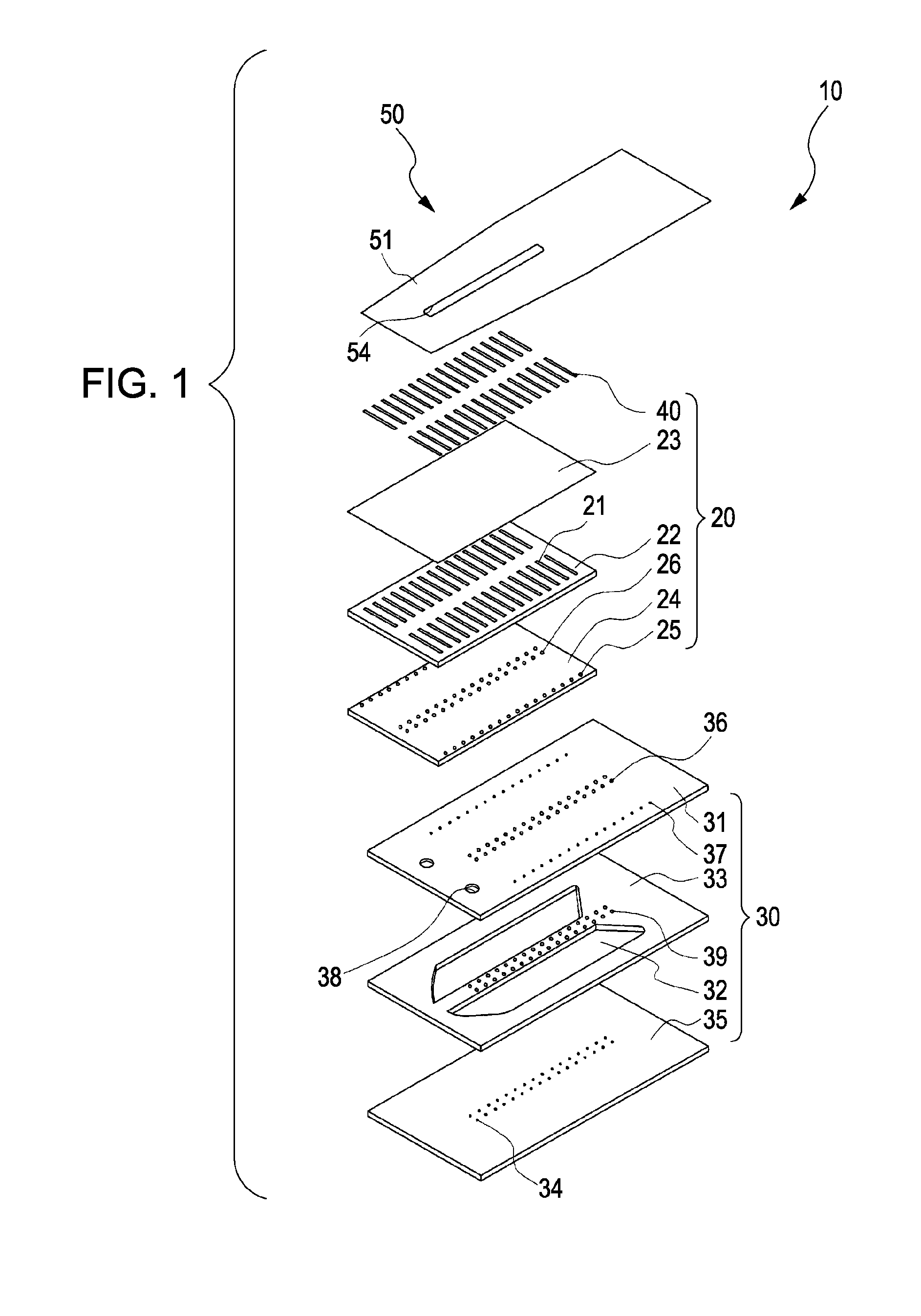
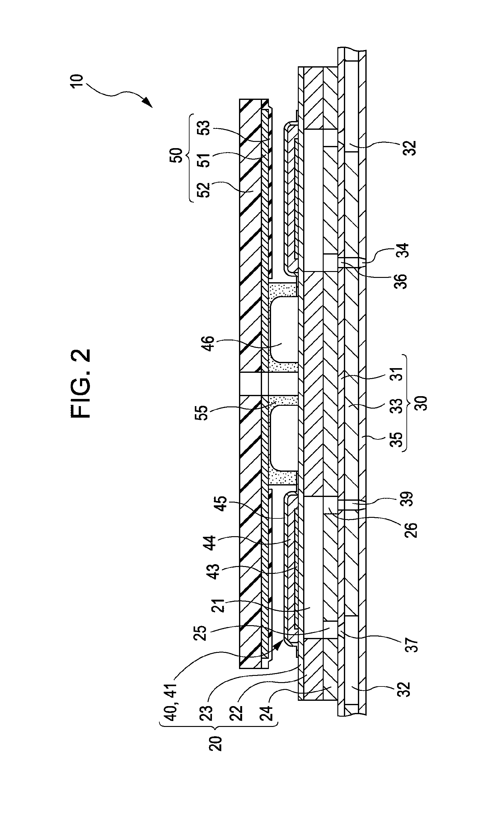
[0027]FIG. 1 shown an exploded perspective view of an ink jet recording head, which is an example of liquid ejecting head relating to a first embodiment. FIG. 2 is a sectional view of the ink jet recording head.
[0028]As shown in these figures, the ink jet recording head 10 comprising an actuator unit 20, a flow channel unit 30 to which the actuator unit 20 is secured, and a wiring substrate 50 connected to the actuator unit 20.
[0029]The actuator unit 20 is an actuator device comprising a piezoelectric element 40. The actuator unit 20 includes a flow channel substrate 22 on which pressure generating chambers 21 are formed, a vibration plate 23 disposed on one surface of the flow channel substrate 22, and a pressure generating chamber bottom plate 24 disposed on the other surface of the flow channel substrate 22.
[0030]The flow channel substrate 22 is made of, for example, a ceramic plate in a thickness about 150 μm, such as an alumina (Al2O3) plate or a zirconia (ZrO2) plate. In the p...
experimental example 1
[0071]Samples 1 to 18 prepared as above were subjected to measurements of the piezoelectric constant d33 (displacement property) in the polarization direction, the dielectric loss (tan δ), the dielectric constant ∈r and the density. The results are shown in Table 1. The piezoelectric constant d33 was measured by using a piezo d33 meter manufactured by UK PIEZOTEST, the dielectric loss tan δ was measured with HP4294A manufactured by Hewlett-Packard, and the density was measured by ARCHIMIDES method at 25° C. The dielectric constant ∈r was measured at 25° C. using HP4294A manufactured by Hewlett-Packard. For Samples 1 to 10, the piezoelectric constant was measured before and after the samples were immersed in water for 3 days, and the reduction of the piezoelectric constant d33 was calculated. The results are shown in Table 2.
[0072]The results show that Samples 4 to 16, which were examples of the invention prepared by adding bismuth manganate and calcium zirconate to a perovskite comp...
experimental example 2
[0078]For Samples 11 to 16, the piezoelectric constants d33 were measured after heating at 25° C., 50° C., 100° C., 150° C., 200° C., 250° C., 300° C., 350° C., 400° C. and 450° C. for 5 minutes each. FIG. 5 shows the results of Sample 15. It was shown that the piezoelectric constants d33 of Samples 11 to 16 were not almost varied even by heating at 200° C., and thus Samples 11 to 16 have superior thermal stability.
PUM
| Property | Measurement | Unit |
|---|---|---|
| thickness | aaaaa | aaaaa |
| thick | aaaaa | aaaaa |
| thickness | aaaaa | aaaaa |
Abstract
Description
Claims
Application Information
 - R&D
- Intellectual Property
- Life Sciences
- Materials
- Tech Scout
- Unparalleled Data Quality
- Higher Quality Content
- 60% Fewer Hallucinations
Browse by: Latest US Patents, China's latest patents, Technical Efficacy Thesaurus, Application Domain, Technology Topic, Popular Technical Reports.
© 2025 PatSnap. All rights reserved.Legal|Privacy policy|Modern Slavery Act Transparency Statement|Sitemap|About US| Contact US: help@patsnap.com


