Wireless communication system with a modulation bandwidth comparable to or exceeding the bandwidth of the transmitter and/or receiver antennas

a wireless communication and modulation bandwidth technology, applied in the field of wireless communication systems, can solve the problems of distorting communication signal caused by antenna frequency response, and achieve the effects of reducing bwant, reducing transmission range or data rate, and increasing the q-factor of the antenna

Active Publication Date: 2011-09-15
OTICON
View PDF9 Cites 63 Cited by
  • Summary
  • Abstract
  • Description
  • Claims
  • Application Information

AI Technical Summary

Benefits of technology

[0008]In systems with electrically small antennas there is a link budget advantage by increasing the antenna Q-factor, i.e. by reducing BWant (cf. an example of such circuit in FIG. 3 representing a second order system for which Qant=f0 / BWant, f0 being the resonance frequency of the antenna / tank circuit). In such case, it can be relevant to use an antenna bandwidth only marginally larger than the signal bandwidth, i.e. k>1, where k=BWant / BWsig. Beyond this point (i.e. k≦1) there may be so much signal distortion, as illustrated in FIG. 5a, 5b, that the link budget becomes worse, i.e. the transmission range or data rate is reduced (if the antenna distortion is not corrected).

Problems solved by technology

However, if the antenna bandwidth is too narrow, the antenna frequency response will distort the communication signal.

Method used


Image

  • Wireless communication system with a modulation bandwidth comparable to or exceeding the bandwidth of the transmitter and/or receiver antennas
  • Wireless communication system with a modulation bandwidth comparable to or exceeding the bandwidth of the transmitter and/or receiver antennas
  • Wireless communication system with a modulation bandwidth comparable to or exceeding the bandwidth of the transmitter and/or receiver antennas

Examples


first embodiment

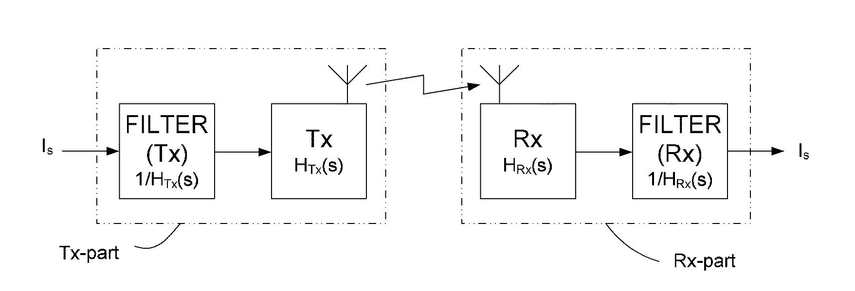
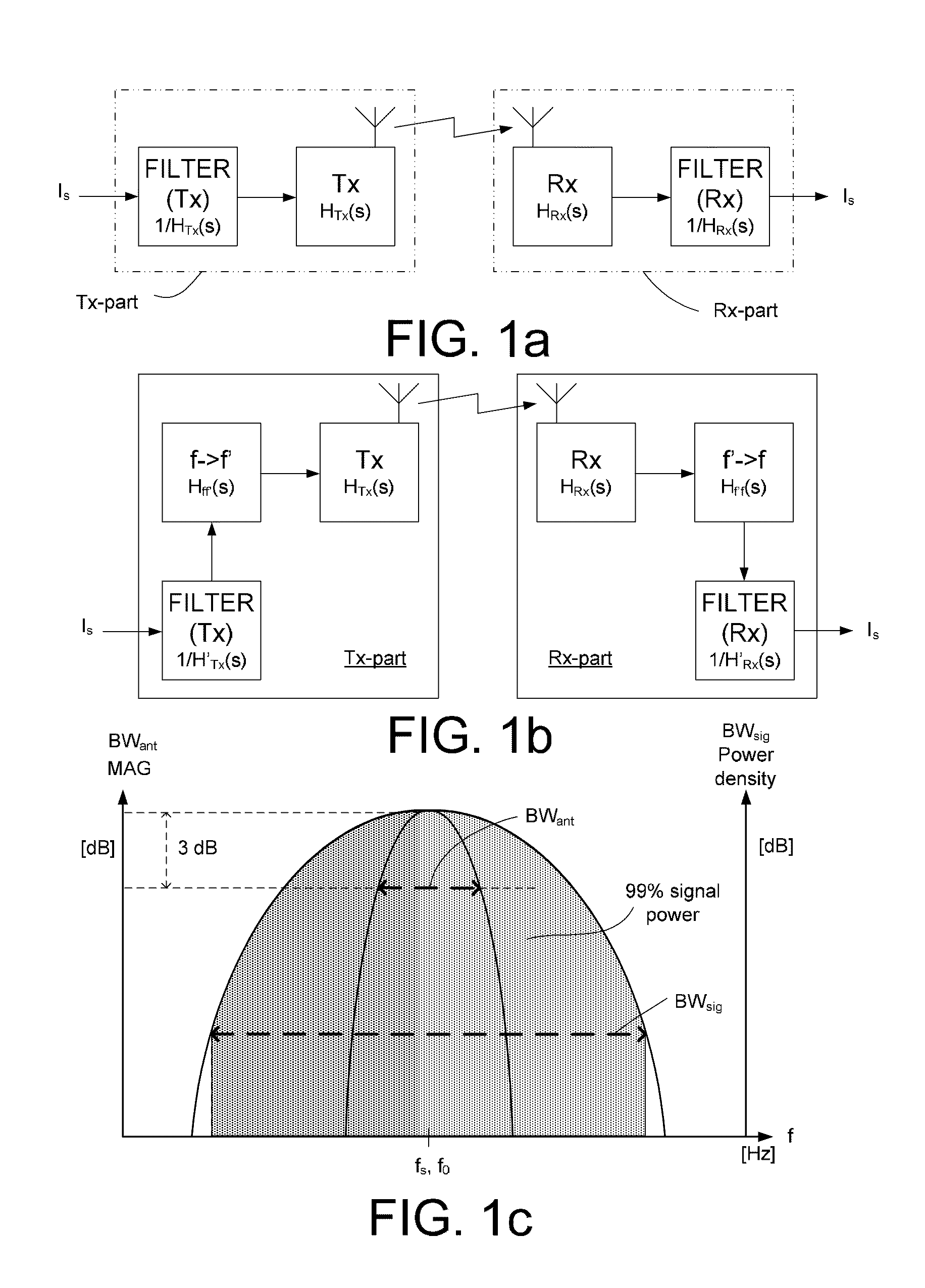
[0084]FIG. 1a is a block diagram of a transmitter part and a receiver part of a first embodiment, The wireless communication system comprises two physically separate devices, a first device comprising a transmitter part comprising a transmitter (Tx) for wirelessly transmitting a modulated electric signal to a receiver part of a second device, the receiver part comprising a receiver (Rx) adapted for receiving the modulated electric signal from the transmitter part. The transmitter (Tx) comprises a Tx-antenna (and tuning circuit) for transmitting the modulated signal. The receiver (Rx) comprises an Rx-antenna (and tuning circuit) for receiving the transmitted signal. It is generally assumed that the Tx- and / or Rx-antennas have a bandwidth BWant, which is substantially equal to or smaller than a modulation bandwidth BWsig of the modulated signal to be transmitted and received by the Tx- and Rx-antennas, respectively (cf. FIG. 1c). The transmitter and receiver parts each further compris...

second embodiment

[0085]FIG. 1b is a block diagram of a transmitter part and a receiver part of a second embodiment, where the transmitter and receiver parts additionally each further comprise a frequency transposition unit (f->f′ and f′->f, respectively, e.g. in the form of a mixer) adapted for transforming a frequency range of an input signal to another frequency range. A signal Is comprising an information to be transmitted from the transmitter part to the receiver part is filtered by the equalization filter (FILTER (Tx)) and the filtered signal is frequency transposed in the Tx-frequency transposition unit (f->f′) and the resulting frequency transposed signal is fed to the Tx-antenna / tank circuit for being transmitted to the receiving part where the corresponding reception and signal processing functions are carried out (in units Rx, f′->f, FILTER(Rx)) to provide the received information signal Is.

[0086]As illustrated in FIG. 1c (showing an exemplary schematic relation between antenna and signal ...


PUM


Abstract

A wireless communication system includes a) a first device having a transmitter part with a Tx-antenna for transmitting an electrical signal having a signal bandwidth BWsig and b) a second device having a receiver part with an Rx-antenna for receiving the transmitted electromagnetic signal. At least one of the Tx- and Rx-antennas is a narrowband antenna having an antenna bandwidth BWant, wherein the Tx- and/or Rx-antenna bandwidths fulfil the relation BWant=k·BWsig. The system is adapted to provide that k is smaller than 1.25, and the antenna bandwidth BWant is defined as the −3 dB bandwidth of the loaded antenna when it is connected to the communication system, and the signal bandwidth BWsig is defined as the bandwidth within which 99% of the desired signal power is located.

Description

TECHNICAL FIELD[0001]The present application relates to antennas for wireless communication systems, e.g. for such systems comprising portable devices, e.g. listening devices. The disclosure relates specifically to a wireless communication system. The application furthermore relates to a radio frequency receiver part and to a radio frequency transmitter part for use in a wireless communication system.[0002]The application moreover relates to the use of a narrowband antenna for transmitting or receiving a signal in a communication system and to a method of calibrating a narrowband antenna / tank frequency transfer function of a wireless communication system.[0003]The disclosure may e.g. be useful in applications involving devices such as handheld communication devices, e.g. listening devices involving wireless communication.BACKGROUND ART[0004]In normal communication systems, antenna bandwidth (BWant) is much larger than the bandwidth of the signal (BWsig) to be transmitted and receive...

Claims


Application Information

Patent Timeline
Patent Type & Authority Applications(United States)
IPC IPC(8): H04B15/00H03K7/06
CPCH04B5/00H04R2225/51H04R25/554H04B5/06Y02D30/70
Inventor CHRISTENSEN, KARE TAISWU, KEHUAIJENSEN, RASMUS GLARBORG
Owner OTICON
Why Eureka
Try Eureka