
Skewed axial fan assembly

Active Publication Date: 2011-09-15
ROBERT BOSCH CORP +1
View PDF5 Cites 20 Cited by
  • Summary
  • Abstract
  • Description
  • Claims
  • Application Information

AI Technical Summary

Benefits of technology

[0010]The invention serves the need for a fan which is skewed to reduce fan noise, but which experiences low radial blade tip deflection. By minimizing radial deflection, the tip gap can be minimized, and performance improved.

Problems solved by technology

This lack of symmetry in the inflow causes unsteady blade loading, and the generation of acoustic tones.
In addition there are several sources of broadband noise.
The fans are typically injection-molded in plastic, a material with limited mechanical properties.
Plastic fans exhibit creep deflection when subject to rotational and aerodynamic loading at high temperature.
This is particularly an issue when the fan is mounted downstream of the heat exchangers, where the fan operates in high-temperature air, and is further subject to radiant heat from various under-hood components.
Unfortunately, large tip gaps generally result in reduced fan efficiency and increased fan noise.
The resulting decrease in performance and increase in noise may not be as important as would be the case with more powerful fan assemblies.
Other fan assemblies, however, consume considerable electric power, and make objectionable noise.
A problem faced by the fan designer is that the blade skew which is desirable for noise reduction often results in increased deflection.
Although U.S. Pat. No. 6,595,744 further describes a fan geometry which minimizes axial deflection of the blade tip for a given skew, it does not prescribe skew distributions which minimize radial deflection.

Method used


Image

  • Skewed axial fan assembly
  • Skewed axial fan assembly
  • Skewed axial fan assembly

Examples


Embodiment Construction

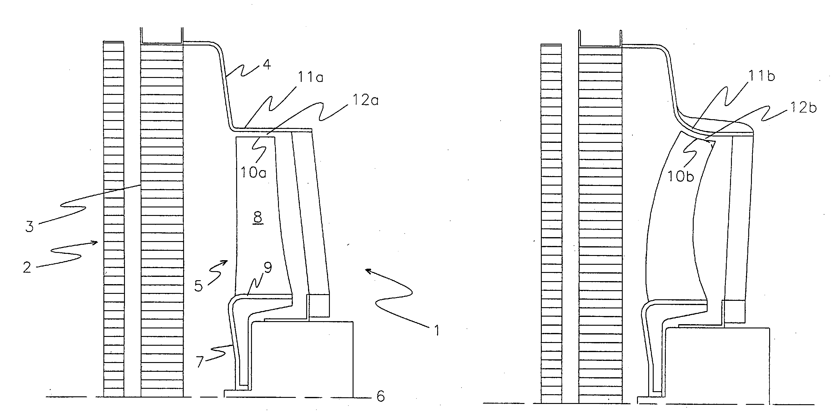
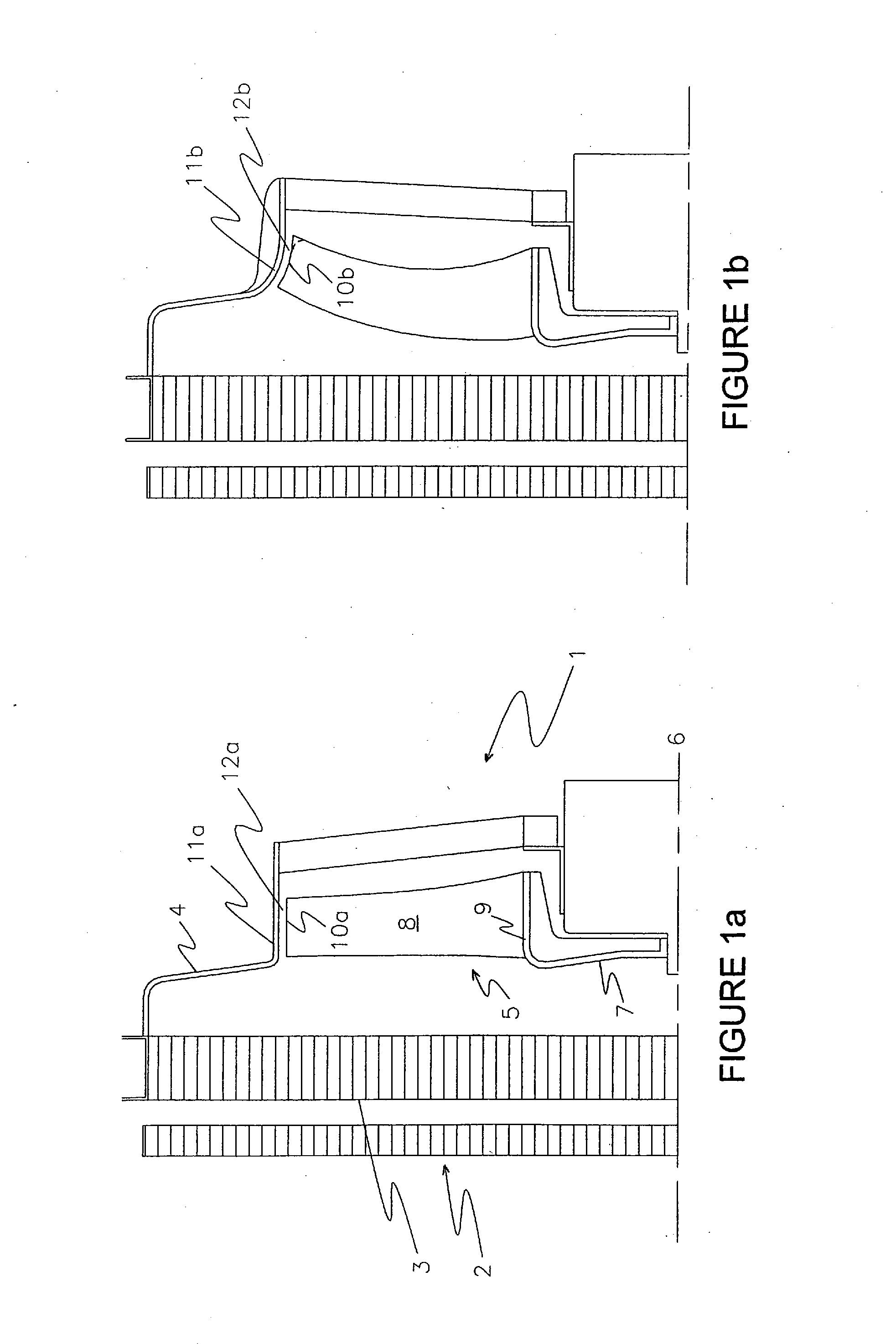
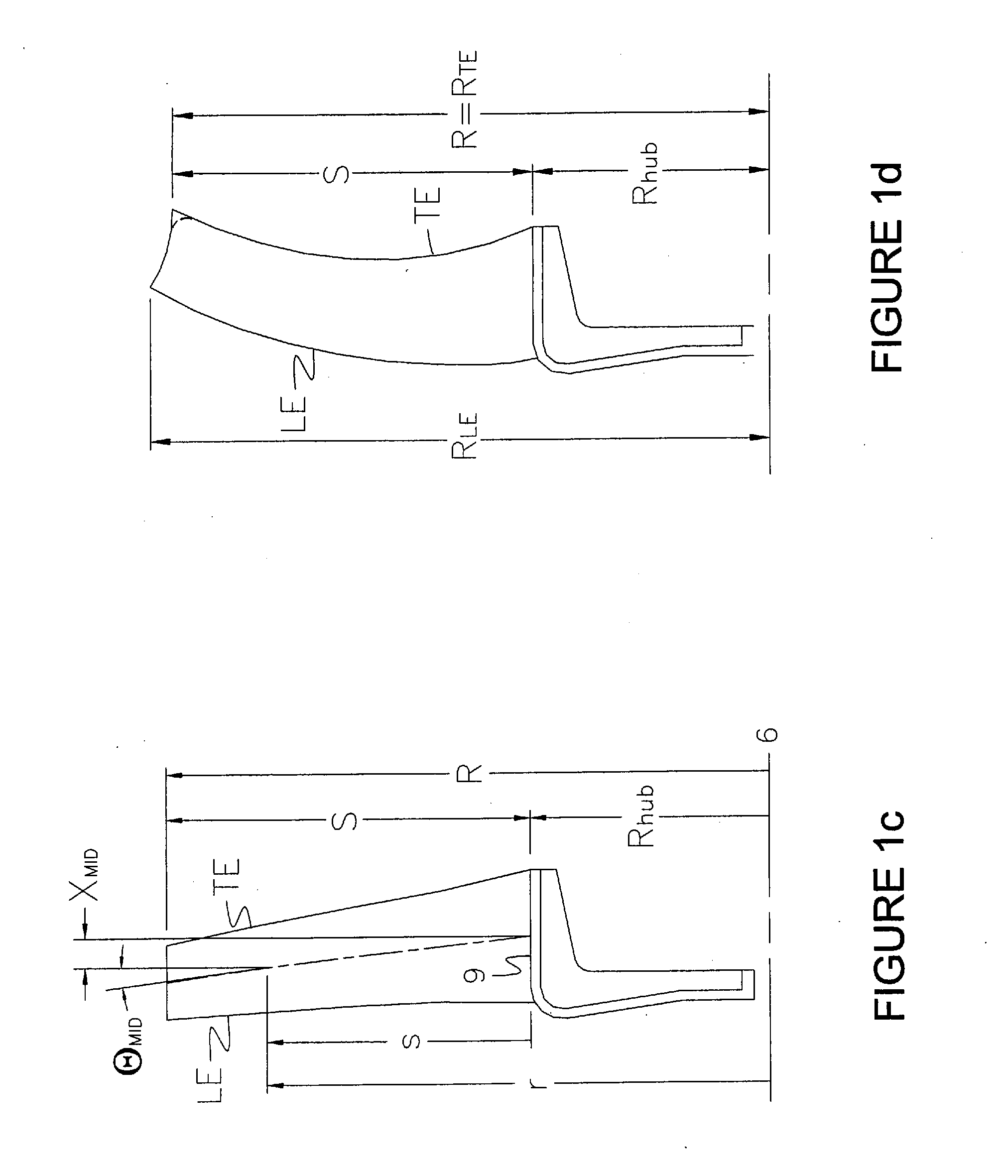
the fan shown in FIG. 2a, with definitions of various geometric parameters.

[0034]FIG. 3a shows an axial projection of a prior-art fan with a blade tip which conforms to a flared shroud and a negative leading-edge sweep angle in a radially outer region.

[0035]FIG. 3b shows an axial projection of one blade of the fan shown in FIG. 3a.

[0036]FIG. 3c is a schematic of the bending forces exerted on the trailing-edge portion of the radially outer region of the blade shown in FIG. 3b.

[0037]FIG. 4a shows an axial projection of a fan according to one construction of the present invention.

[0038]FIG. 4b shows an axial projection of one blade of the fan shown in FIG. 4a.

[0039]FIG. 5a shows an axial projection of a fan according to one construction of the invention.

[0040]FIG. 5b shows an axial projection of one blade of the fan shown in FIG. 5a.

[0041]FIG. 6 shows a plot of calculated radial deflection of the blade tip for the fans shown in FIGS. 3, 4, and 5.

DETAILED DESCRIPTION

[0042]FIG. 1a sh...


PUM


Abstract

A free-tipped axial fan assembly has a skew distribution which reduces fan noise while minimizing radial tip deflection. The difference between the maximum value of leading-edge skew and the value of leading-edge skew at the fan radius is at least 10 degrees. The ratio of the difference of the leading-edge skew between the maximum value and the value at the fan radius to the difference of the trailing-edge skew between the maximum value and the value at the fan radius is at least 2.5.

Description

CROSS-REFERENCE TO RELATED APPLICATIONS[0001]This application claims priority to U.S. Provisional Patent Application No. 61 / 312,487 filed Mar. 10, 2010, the entire contents of which are hereby incorporated by reference.BACKGROUND[0002]This invention relates generally to free-tipped axial-flow fans, and more particularly to free-tipped fans that may be utilized as automotive engine-cooling fans.[0003]Engine-cooling fans are used in automotive vehicles to move air through a set of heat exchangers which typically includes a radiator to cool an internal combustion engine, an air-conditioner condenser, and perhaps additional heat exchangers. These fans are generally enclosed by a shroud which serves to reduce recirculation and to direct air between the heat exchangers and the fan.[0004]The shroud plenum (that portion of the shroud adjacent to the heat exchangers) is generally rectangular and the inflow to the fan is not axisymmetric. The radiator typically has a fin-and-tube structure wh...

Claims


Application Information

Patent Timeline
IPC IPC(8): F04D29/38
CPCF04D29/386Y10S416/05Y10S416/02F04D29/164F04D19/00F04D29/32F04D29/38F04D29/54
Inventor VAN HOUTEN, ROBERT J.
Owner ROBERT BOSCH CORP
Learn More