Medical device including an air evacuation system

a medical device and air evacuation technology, applied in the field of medical devices, can solve the problems of inaccuracy of dosage measurements and other issues, expulsion of a portion of liquid aspirated into the syringe barrel, etc., and achieve the effect of preventing fluid communication

Active Publication Date: 2011-09-15
BECTON DICKINSON & CO
View PDF32 Cites 20 Cited by
  • Summary
  • Abstract
  • Description
  • Claims
  • Application Information

AI Technical Summary

Benefits of technology

In one or more embodiments according to a fourth aspect, the porous portion is formed from a swellable polymer and is disposed adjacent to the plug. The porous portion forms an expandable barrier between the head of the plug and the opening. Upon contact with a liquid, the porous portion expands and applies a force on the head in a proximal direction that causes the channel to be positioned proximally adjacent the opening and allows the elongate core to form a fluid-tight seal with the opening, preventing fluid communication between the opening and the stopper cavity.
The plunger rod according to one or more embodiments of a fourth aspect of the present invention may include a sealing portion for forming a fluid-tight seal with the interior surface of the barrel and is moveable within the chamber in the proximal and distal directions independently from the stopper assembly. In such embodiments, upon application of a force on the plunger rod in the proximal direction, the plunger rod moves in the proximal direction and creates a vacuum within the stopper cavity that draws air from the chamber through the channel of the plug into the stopper cavity. In one or more embodiments, contact between the liquid and the porous portion causes the porous portion to expand and apply a force on the head in a proximal direction that causes the channel to be positioned proximally adjacent the opening and prevents fluid communication between the opening and the stopper cavity. The application of a force on t...

Problems solved by technology

The presence of air within the syringe barrel can result in inaccurate dosage measurements and other issues.
This expulsion process, however, can result in the expulsion of a portion of the liquid aspirated into the syringe barrel.
In addition, this method of removing air from...

Method used


Image

  • Medical device including an air evacuation system
  • Medical device including an air evacuation system
  • Medical device including an air evacuation system

Examples


Embodiment Construction

Before describing several exemplary embodiments of the invention, it is to be understood that the invention is not limited to the details of construction or process steps set forth in the following description. The invention is capable of other embodiments and of being practiced or being carried out in various ways. It is to be understood that the configurations shown in FIGS. 1-84 are merely exemplary, and the components can be different in shape and size than shown.

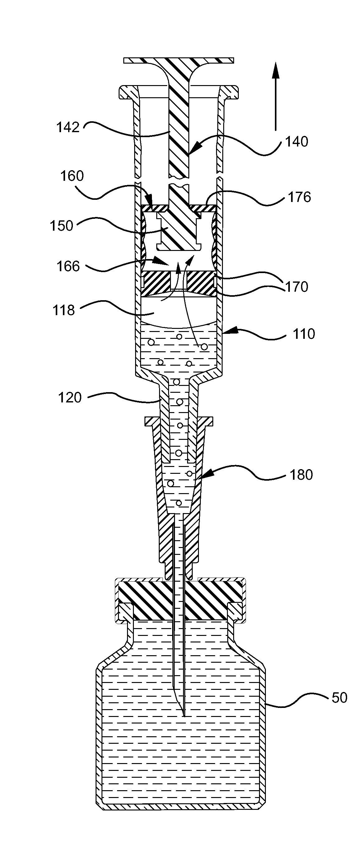
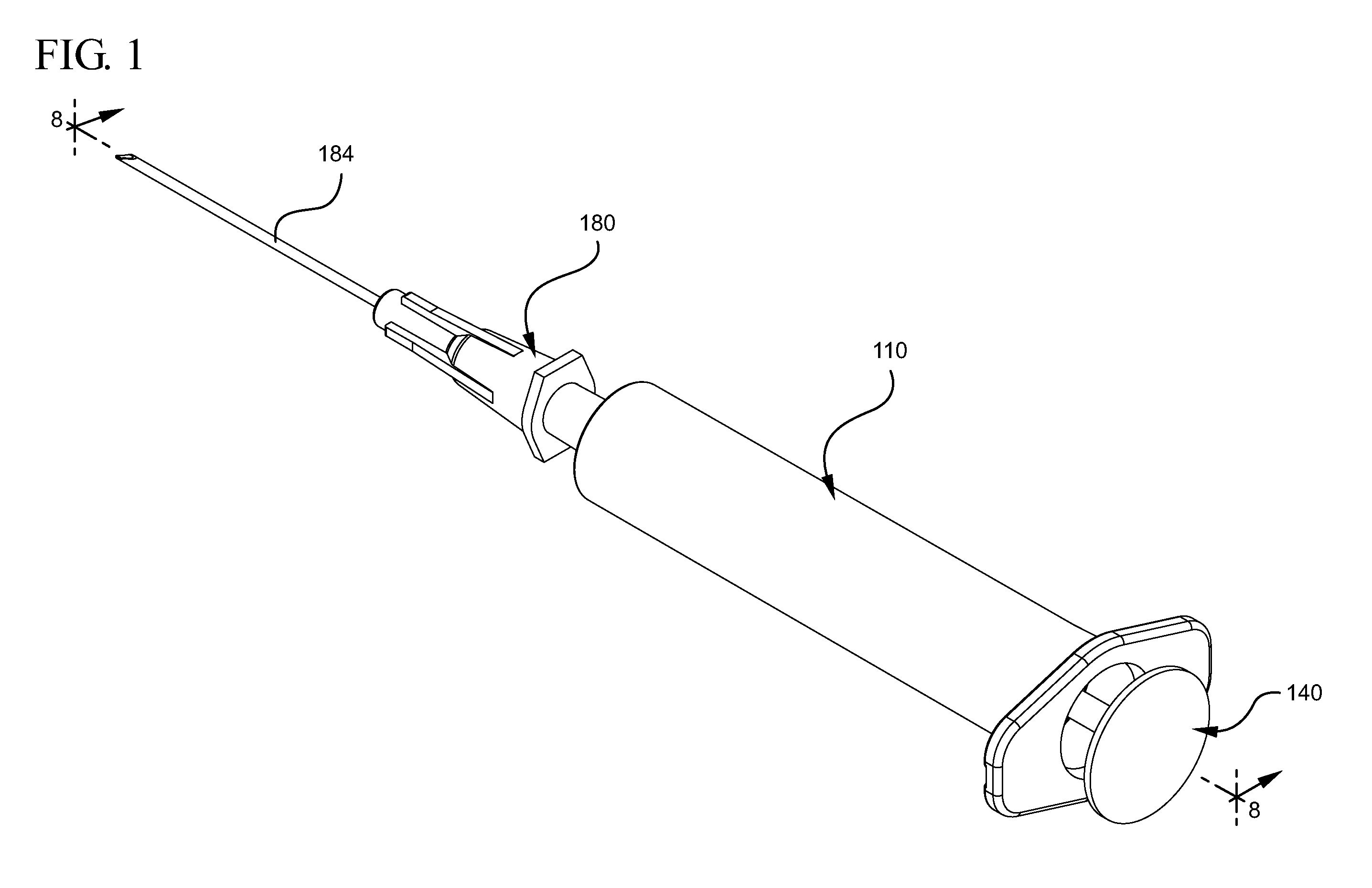
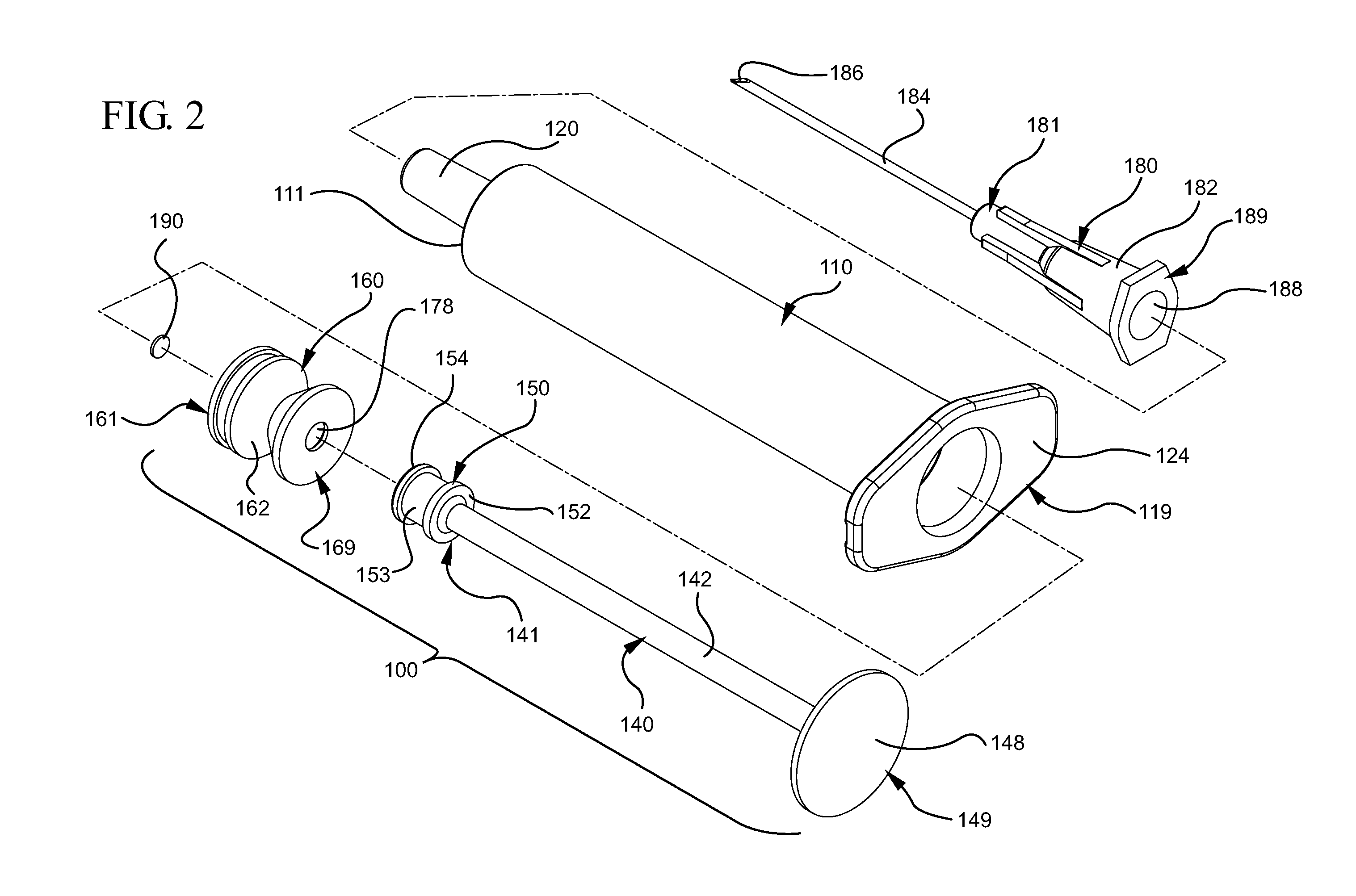
The embodiments of the present invention described herein, with specific reference to various aspects, provides for a medical device including syringe barrel or other containers to draw liquid from a source into the syringe barrel. The medical devices described herein generally include a plunger rod and stopper assembly and means to actively remove or evacuate air from the liquid drawn into the syringe barrel or other container. The embodiments of the medical device may be used with other types of containers, in additio...


PUM

PropertyMeasurementUnit
Forceaaaaaaaaaa
Pressureaaaaaaaaaa
Distanceaaaaaaaaaa

Abstract

Medical device assemblies capable of aspirating liquid into a syringe barrel or other medical devices while evacuating any air from the syringe are described. An exemplary medical device includes a syringe barrel, plunger rod and stopper assembly having an air permeable and liquid impermeable porous portion and structure for forming a vacuum within either the stopper or the plunger rod. Described is a medical device including a syringe barrel, plunger rod and stopper assembly having an air permeable and liquid impermeable porous portion and structure for forming a vacuum within chamber between the stopper and plunger rod wherein the plunger rod includes a sealing edge and is moveable relative to the stopper. Exemplary medical devices may include a vent for allowing air that permeates through the porous portion to escape to atmosphere. Methods for aspirating a syringe barrel with a liquid are also provided.

Description

TECHNICAL FIELDAspects of the present invention relate to medical devices for use with containers capable of evacuating air trapped within the container while filling the container with liquid.BACKGROUNDSyringe barrels contain, store, transfer and measure liquids, typically containing medicaments or other fluids for delivery to a patient. Medical devices, including plunger rods and stoppers, are used to aspirate and expel liquid from syringe barrels. During aspiration, air can become trapped within the syringe barrel. The presence of air within the syringe barrel can result in inaccurate dosage measurements and other issues.Typically, air is removed from syringe barrels, by inverting the syringe barrel to force the air trapped within the barrel to the opening through which the fluid is aspirated. The air is then expelled through the opening by applying a force on the plunger rod in the distal direction. This expulsion process, however, can result in the expulsion of a portion of the...

Claims


Application Information

Patent Timeline
IPC IPC(8): A61M5/38A61M5/36B65B3/04
CPCA61M5/1782A61M5/3145A61M5/31511A61M5/31513A61M5/36A61B5/153A61M2005/3123A61M2005/31516A61B5/15003A61B5/150213A61B5/150236A61M2005/3112
Inventor LUM, CHEE LEONGSOLTZ, MICHAEL
Owner BECTON DICKINSON & CO
Why Eureka
Try Eureka