Wireless power feeder, wireless power receiver, and wireless power transmission system
- Summary
- Abstract
- Description
- Claims
- Application Information
AI Technical Summary
Benefits of technology
Problems solved by technology
Method used
Image
Examples
first embodiment
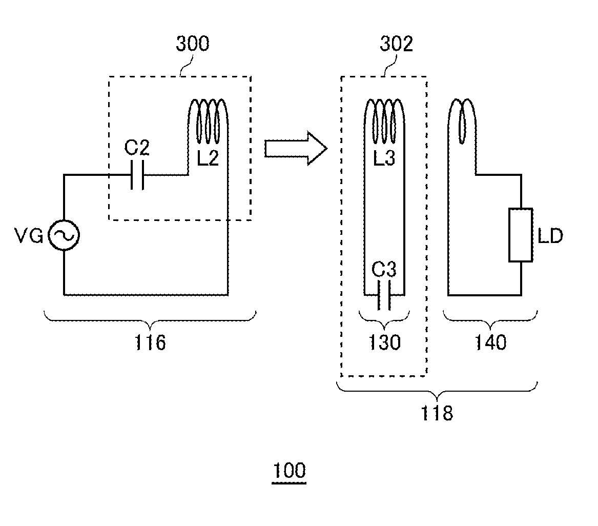
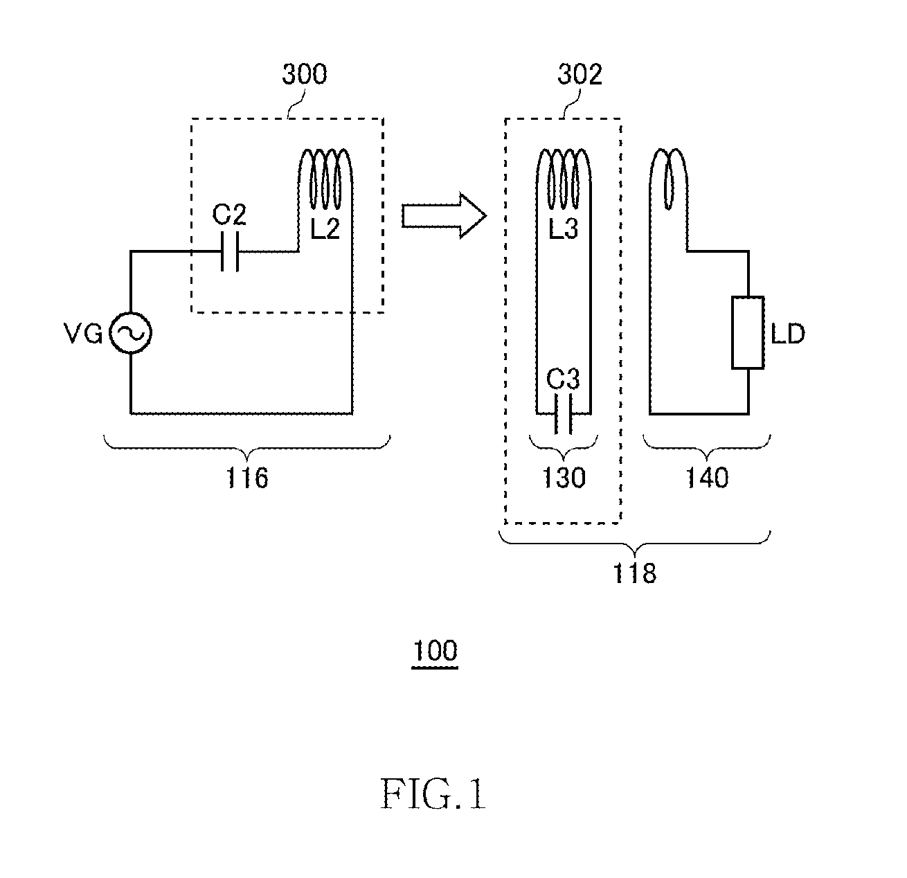
[0074]FIG. 1 is a view illustrating operation principle of a wireless power transmission system 100 according to a first embodiment and a third embodiment to be described later. The wireless power transmission system 100 includes a wireless power feeder 116 and a wireless power receiver 118. The wireless power feeder 116 includes a power feeding LC resonance circuit 300. The wireless power receiver 118 includes a receiving coil circuit 130 and a loading circuit 140. A power receiving LC resonance circuit 302 is formed by the receiving coil circuit 130.
[0075]The power feeding LC resonance circuit 300 includes a capacitor C2 and a feeding coil L2. The power receiving LC resonance circuit 302 includes a capacitor C3 and a receiving coil L3. The values of the capacitor C2, power feeding coil L2, capacitor C3, and power receiving coil L3 are set such that the resonance frequencies of the power feeding LC resonance circuit 300 and power receiving LC resonance circuit 302 coincide with eac...
second embodiment
[0153]FIG. 14 is a view illustrating operation principle of the wireless power transmission system 100 according to a second embodiment and a fourth embodiment to be described later. As in the case of the first embodiment, the wireless power transmission system 100 according to the second embodiment includes the wireless power feeder 116 and wireless power receiver 118. However, although the wireless power receiver 118 includes the power receiving LC resonance circuit 302, the wireless power feeder 116 does not include the power feeding LC resonance circuit 300. That is, the power feeding coil L2 does not constitute a part of the LC resonance circuit. More specifically, the power feeding coil L2 does not form any resonance circuit with other circuit elements included in the wireless power feeder 116. No capacitor is connected in series or in parallel to the power feeding coil L2. Thus, the power feeding coil L2 does not resonate in a frequency at which power transmission is performe...
third embodiment
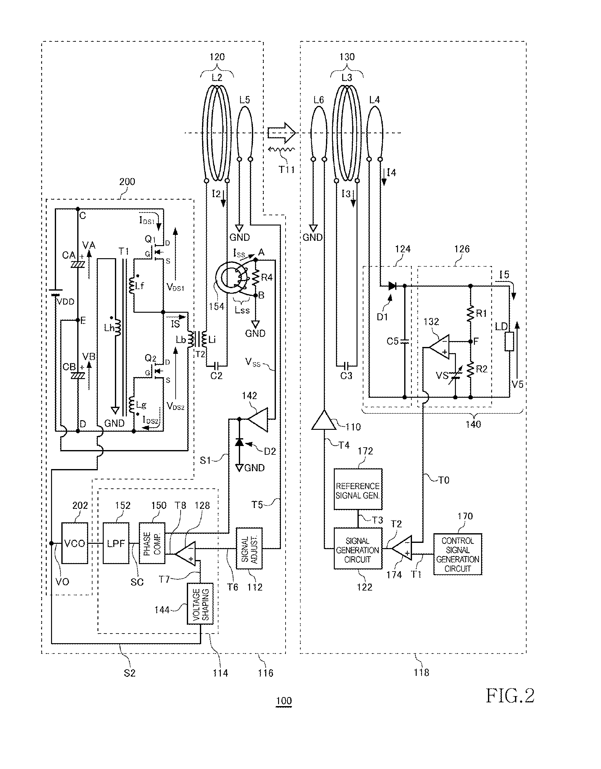
[0157]FIG. 16 is a system configuration view of the wireless power transmission system 100 according to a third embodiment. The wireless power transmission system 100 of the third embodiment operates based on the operational principle described using FIG. 1. That is, the power feeding coil L2 supplies AC power of the resonance frequency fr1 to the power receiving coil L3 while resonating at the resonance frequency fr1. The wireless power transmission system 100 includes the wireless power feeder 116 and wireless power receiver 118. The wireless power feeder 116 includes, as basic components, the power transmission control circuit 200, feeding coil circuit 120, signal adjustment circuit 112, and phase detection circuit 114. The wireless power receiver 118 includes, as basic components, the receiving coil circuit 130, loading circuit 140, and signal generation circuit 122. The wireless power feeder 116 according to the third embodiment also directly drives the power feeding coil L2 wi...
PUM
 Abstract
Description
Claims
Application Information
 - R&D
- Intellectual Property
- Life Sciences
- Materials
- Tech Scout
- Unparalleled Data Quality
- Higher Quality Content
- 60% Fewer Hallucinations
Browse by: Latest US Patents, China's latest patents, Technical Efficacy Thesaurus, Application Domain, Technology Topic, Popular Technical Reports.
© 2025 PatSnap. All rights reserved.Legal|Privacy policy|Modern Slavery Act Transparency Statement|Sitemap|About US| Contact US: help@patsnap.com


