

Device and method for measuring the position of at least one moving object in a three-dimensional grid
- Summary
- Abstract
- Description
- Claims
- Application Information
AI Technical Summary
Problems solved by technology
Method used
Image

Examples
second embodiment
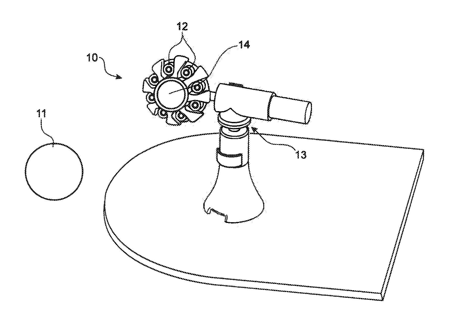
[0009]In a second embodiment, the movable base comprises a universal joint type mechanical link. An array of such movable bases can thus be used to track a plurality of targets.
[0010]Advantageously, the laser sources array is a VCSEL array and the laser sources are laser diodes. The optical head may thus comprise:
collimated laser diodes,
a photodiode,
an analog multiplexer,
a transimpedance amplifier and inverter,
[0011]Advantageously, the control electronics comprise:
a digital-analogue converter,
an analog-digital converter,
a digital input / output module,
a communication module,
a regulation and power control circuit.
[0012]Advantageously, the device according to the invention comprises a lenses array positioned in front of the laser sources array and movable in a linear manner in front of same.
[0013]The invention also relates to a method for measuring the position of at least one moving object in a three-dimensional grid using a device for measuring the ...
first embodiment
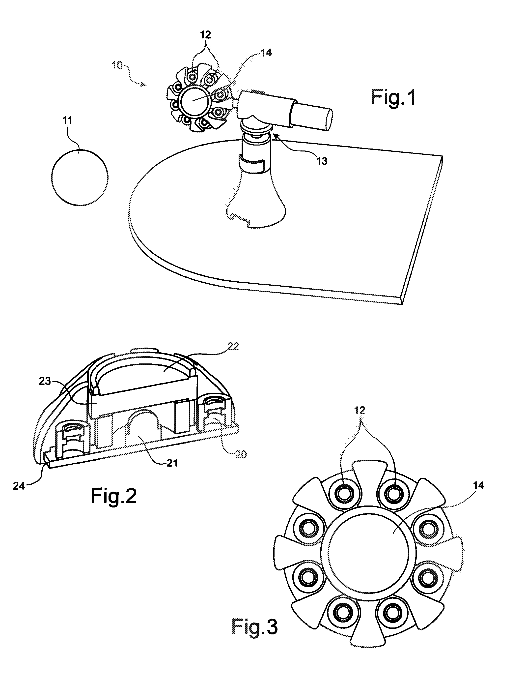
[0016]FIG. 1 illustrates the device according to the invention.
[0017]FIG. 2 illustrates sectional view of the optical head of the device according to the invention illustrated in FIG. 1.
[0018]FIG. 3 illustrates the arrangement of the various laser sources of an array in this optical head.
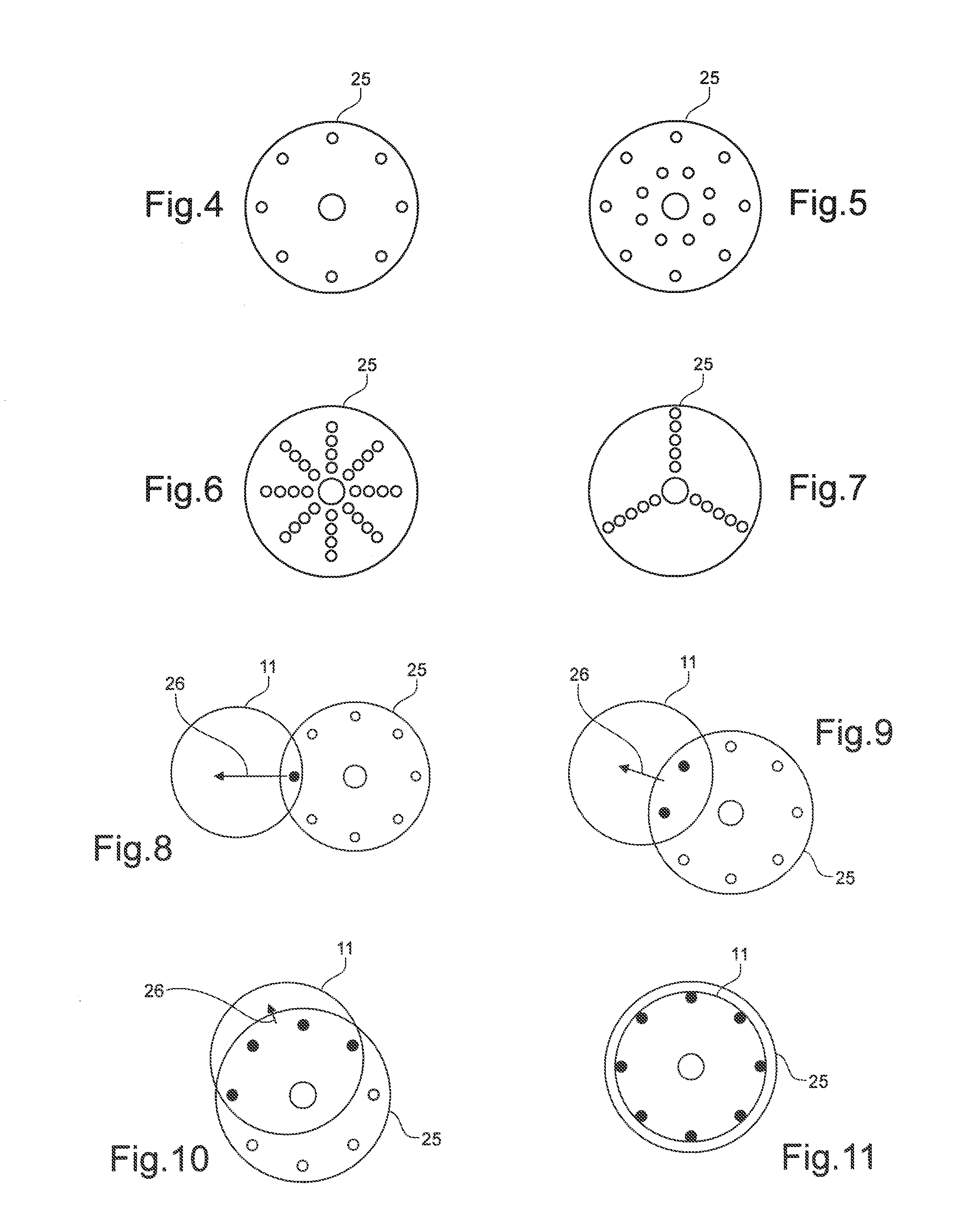
[0019]FIGS. 4 to 7 illustrate various laser imprint configurations.
[0020]FIGS. 8 to 11 illustrate various positions between the target and the optical head.
[0021]FIGS. 12A and 12B illustrate the current / voltage characteristics and the electrical diagram of the laser diode multiplexing, respectively.
[0022]FIG. 13 illustrates the optical head processing algorithm.
[0023]FIGS. 14A, 14B and 15 illustrate the operation of the movable base in the first embodiment of the device according to the invention.
[0024]FIGS. 16A and 16B shows a second embodiment of the device according to the invention with a movable base with two degrees of freedom. FIG. 17 shows an array configuration of this second embodiment for...
PUM
 Abstract
Description
Claims
Application Information