Optical filter and analytical instrument

an optical filter and filter body technology, applied in the field of optical filters and analytical instruments, can solve the problems of diaphragm section breakage and strength degradation, and achieve the effects of reducing the maximum applied voltage, enhancing the strength of the diaphragm section, and preventing the diaphragm section from deteriorating strength

Inactive Publication Date: 2011-09-22
SEIKO EPSON CORP
View PDF9 Cites 6 Cited by
  • Summary
  • Abstract
  • Description
  • Claims
  • Application Information

AI Technical Summary

Benefits of technology

[0007]An advantages of some aspects of the invention is to provide an optical filter and an optical module equipped with the optical filter each capable of preventing the degradation of strength of the diaphragm section even in the case of t

Problems solved by technology

However, thinning the diaphragm section causes degradation of strength, and in the optical filter repeatedly varying the gap stress is applied to the diaphragm

Method used


Image

  • Optical filter and analytical instrument
  • Optical filter and analytical instrument
  • Optical filter and analytical instrument

Examples


Embodiment Construction

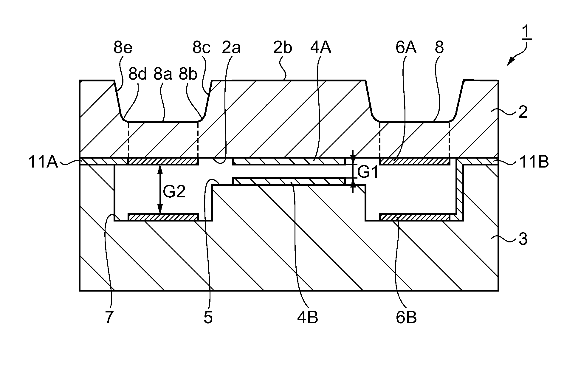
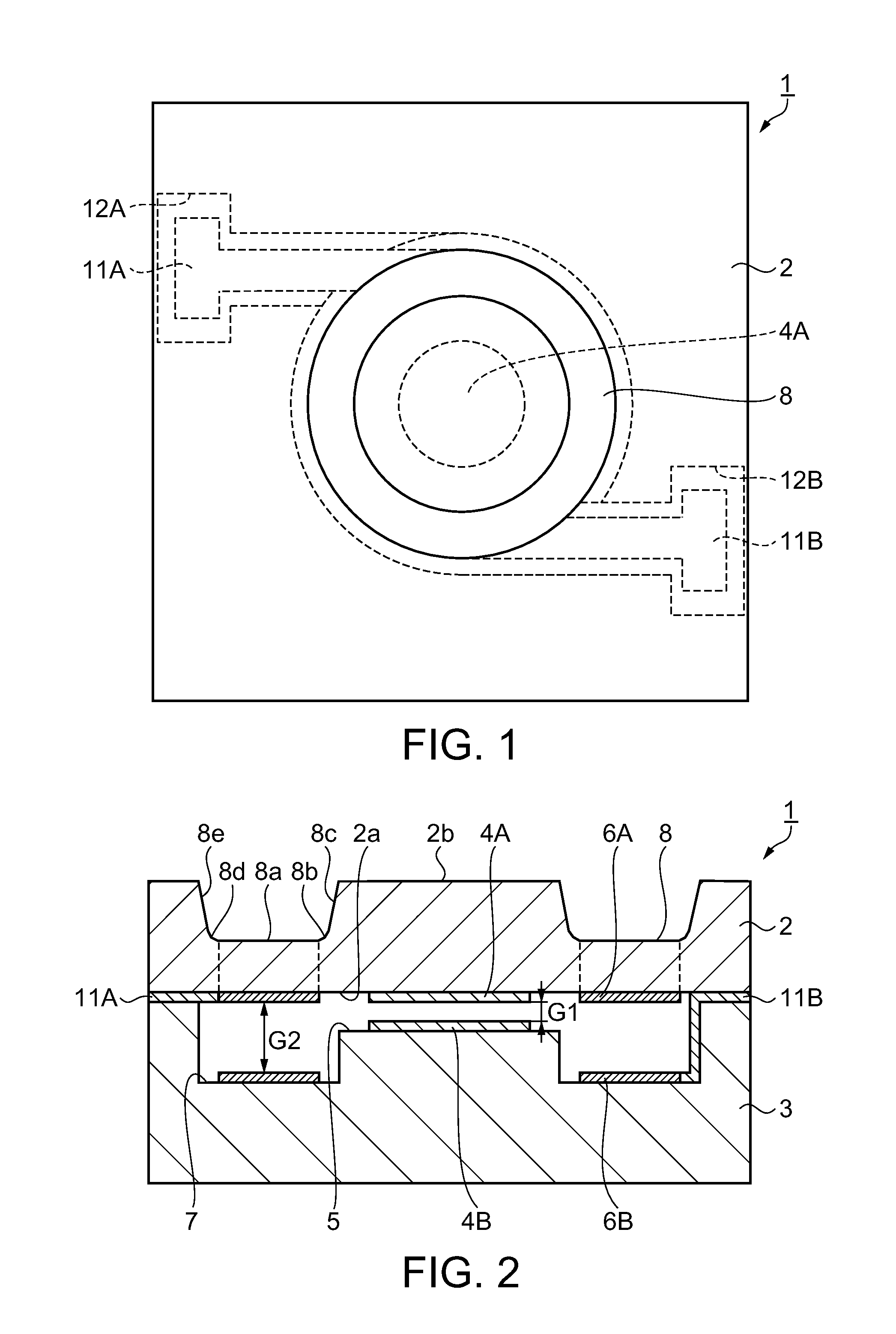
[0029]Hereinafter, an optical filter according to an embodiment of the invention will be explained. Here, as the optical filter, an optical filter of an air-gap type and of an electrostatic-drive type will be explained.

[0030]In FIGS. 1 and 2, the reference numeral 1 denotes an optical filter of the air-gap type and of the electrostatic-drive type. The optical filter 1 is composed of an upper substrate 2, a lower substrate 3 bonded (or joined with an adhesive) to the upper substrate 2 in the state of being opposed thereto, a mirror 4A (an upper mirror) having a circular shape disposed at a central portion of an opposed surface 2a of the upper substrate 2, the opposed surface 2a being opposed to the lower substrate 3, a mirror 4B (a lower mirror) having a circular shape disposed at a central portion of a bottom surface of a first recessed section 5 formed at a central portion of a surface of the lower substrate 3, the surface being opposed to the upper substrate 2, so as to be opposed...


PUM


Abstract

An optical filter includes: a lower substrate; a lower mirror provided to the lower substrate; a lower electrode provided to the lower substrate; an upper substrate disposed so as to be opposed to the lower electrode; an upper mirror provided to the upper substrate, and opposed to the lower mirror; and an upper electrode provided to the upper substrate, and opposed to the lower electrode, wherein the upper substrate has a groove surrounding the upper mirror in a plan view, the groove includes a first side surface section, a second side surface section, a bottom surface section, a first end section located between the first side surface section and the bottom surface section, and a second end section located between the second side surface section and the bottom surface section, in a cross-sectional view, and the first end section and the second end section each have a curved surface.

Description

BACKGROUND[0001]1. Technical Field[0002]The present invention relates to an optical filter and an analytical instrument.[0003]2. Related Art[0004]In the past, as an optical filter for selecting a light beam having a target wavelength from the incident light beams and then emitting the light beam, there has been known an optical filter of an air-gap type and of an electrostatic-drive type, in which a pair of substrates are disposed so as to be opposed to each other, each of the surfaces of the substrates opposed to each other is provided with a mirror, electrodes are respectively disposed in the peripheries of the mirrors, a diaphragm section is disposed in the periphery of one of the mirrors, and the diaphragm section is displaced due to electrostatic force generated between the electrodes to thereby vary the gap (air gap) between the mirrors, thus taking out the light beam having a desired wavelength (e.g., JP-A-2003-57438).[0005]In such an optical filter, it is required to control...

Claims


Application Information

Patent Timeline
IPC IPC(8): G02B5/28
CPCG02B5/284G02B26/001G03F7/70575G02F2001/213G02F1/21G02F1/213G02B5/201H01L21/0274G01J3/26
Inventor SHINTO, SUSUMUYAMAZAKI, SEIJI
Owner SEIKO EPSON CORP
Why Eureka
Try Eureka