Vortex dynamics turbine

a turbine and dynamics technology, applied in the direction of brake pipes, liquid fuel engine components, non-positive displacement fluid engines, etc., can solve the problems of disproportionate increase in energy cost (coe) to their performance improvement contribution, and achieve low cost, suppress adverse pressure gradients, and enhance aerodynamic characteristics

Inactive Publication Date: 2011-09-22
AEROVORTEX MILLS
View PDF4 Cites 57 Cited by
  • Summary
  • Abstract
  • Description
  • Claims
  • Application Information

AI Technical Summary

Benefits of technology

[0006]The present invention is a device which consists of a vortex generator combined with a vortex accelerator that intercepts or compresses the generated vortical flow. The use of the fore mentioned device on the airfoil surface, preferably on its high pressure surface or side, generates vorticity which can be used to transfer momentum to the surface flow in a way that enhances the aerodynamic characteristics by suppressing adverse pressure gradients. Also, the compression of the generated vorticity by an active/passive vortex accelerator surface protrusion on either the low or high pressure blade surface, constitutes a simple, low cost, fast response and highly effective method for controlling enhanced airfoil circulation. Additionally, the use of the vortex accelerator for capturing the generated vorticity, reduces the drag penalty associated with the vortex generator.
[0007]By way of example, and not a limitation, a plurality of the above mentioned vorticity devices (vortex generator coupled with a vortex accelerator) are installed on the high pressure or impact surface of each blade of a wind or underwater turbine. Preferably, these devices are mounted close to the trailing edge of each blade, which can be either sharp or blunt. The generation and control of vorticity by ...

Problems solved by technology

Despite their promising test results, all of the above-mentioned techniques, incur a high drag penalty or add weight and complexity which increase the Cost of Energy (COE) disproportionately to their performance improvement contribution.
However, their eve...

Method used


Image

  • Vortex dynamics turbine
  • Vortex dynamics turbine
  • Vortex dynamics turbine

Examples


Embodiment Construction

is given in the sections that follow. The purpose of this description is to fully disclose its preferred embodiments without placing limitations thereon.

[0009]The invention will now be described with reference to the accompanying drawings.

BRIEF DESCRIPTION OF THE DRAWINGS

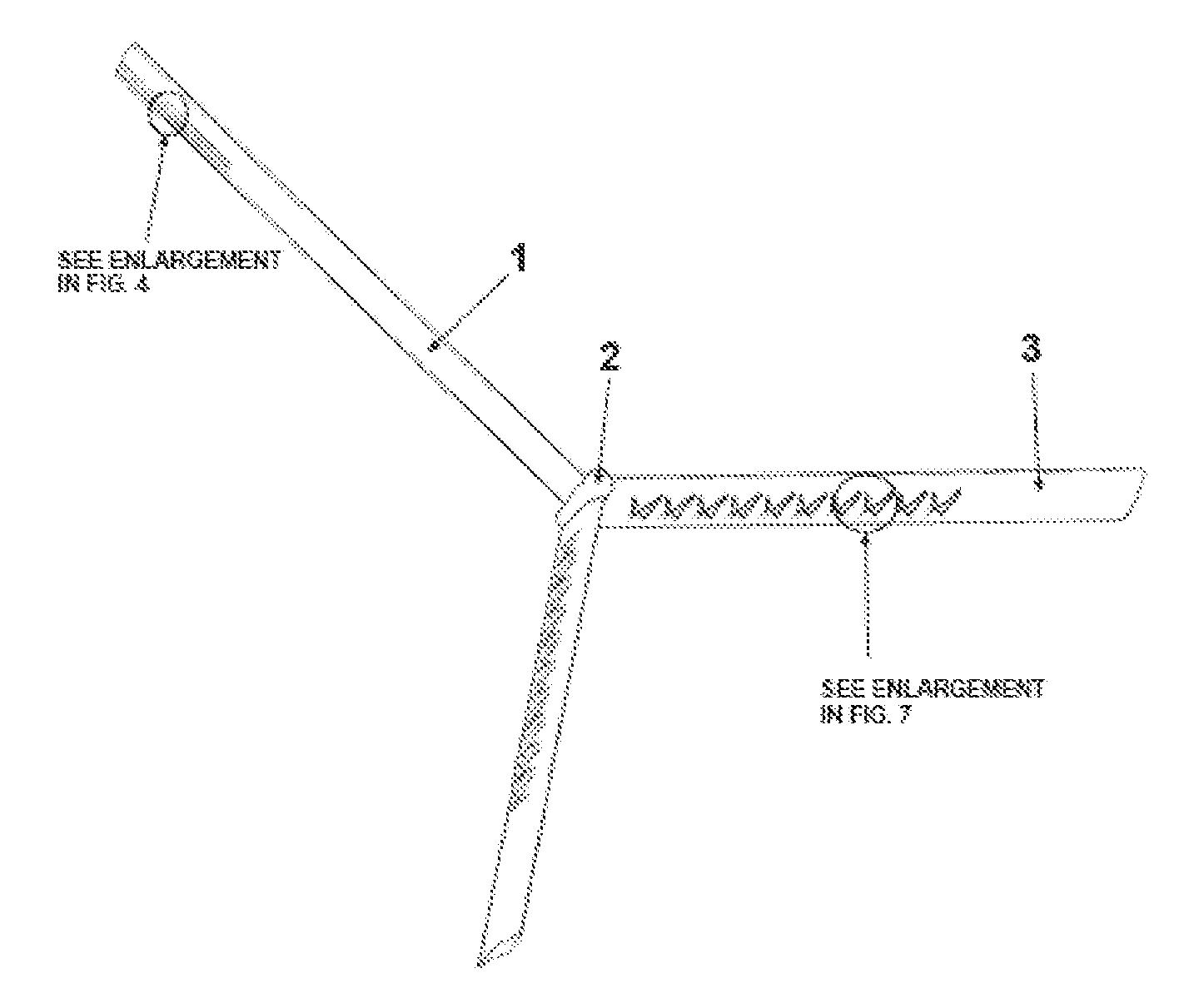
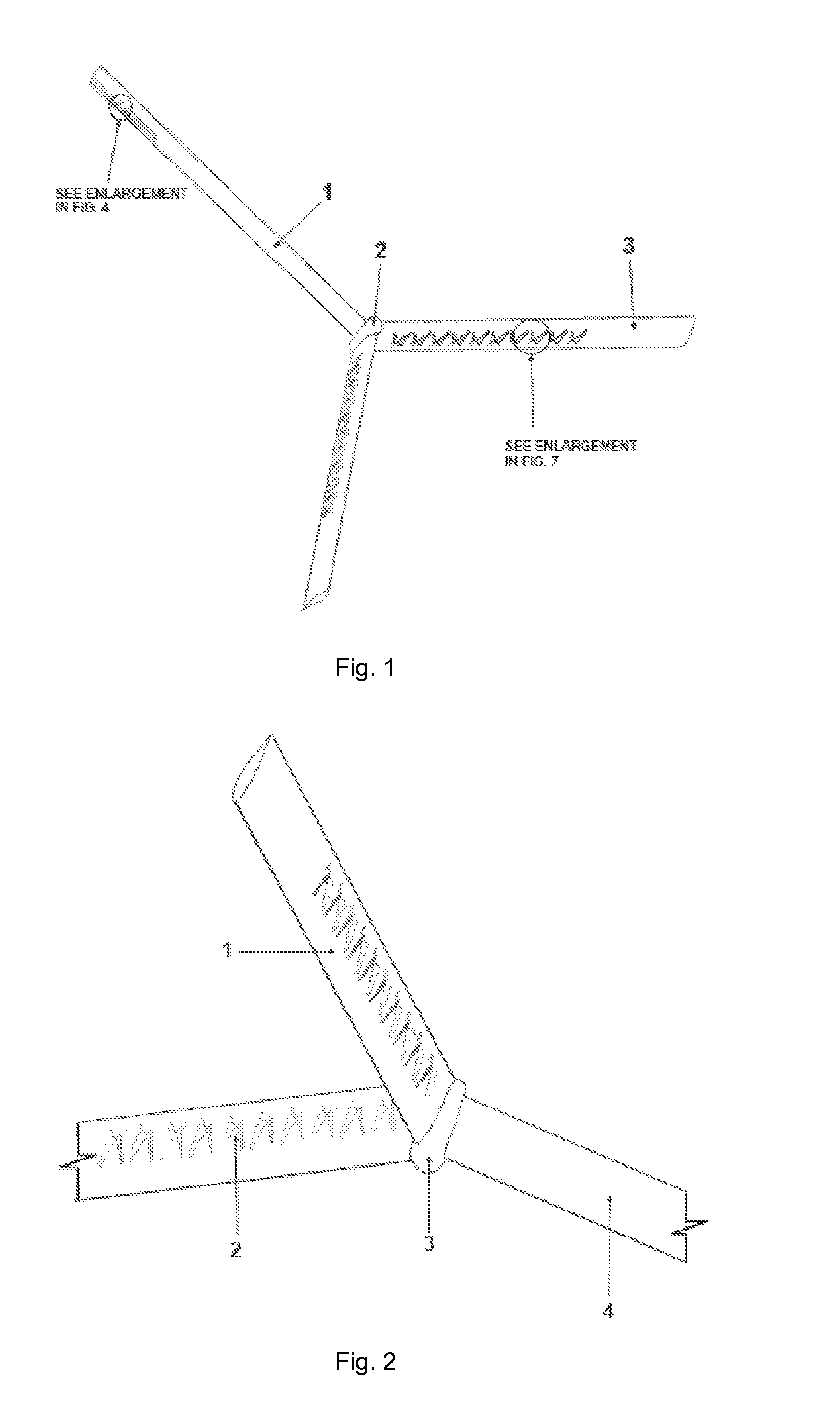
[0010]FIG. 1 is a schematic view of a three-blade turbine with the variant 1 of vorticity-induced suction devices attached on the high pressure surface of the blades, and suction holes on the low-pressure surface of the blade at the tip;

[0011]FIG. 2 is a schematic close-up view of the variant 1 suction devices on the high pressure surface of the three-blade turbine;

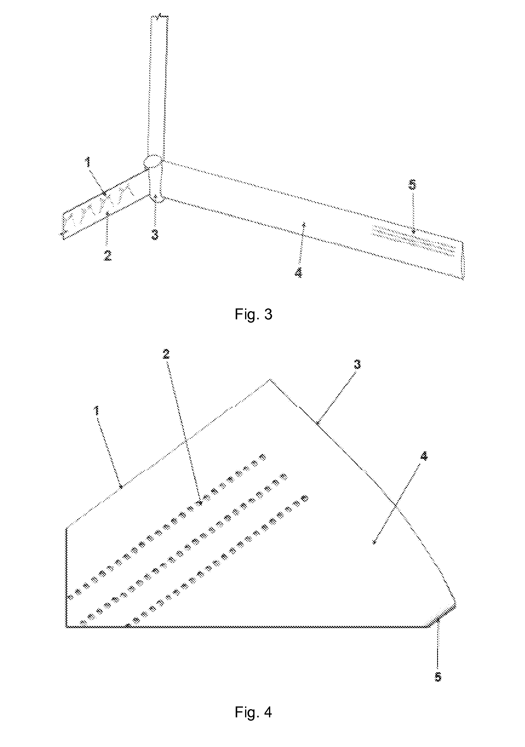
[0012]FIG. 3 is a schematic view from the rear of a three-blade turbine, showing the suction holes at the tip of the low-pressure surface of a blade and the variant 1 of vorticity-induced suction devices on the high pressure surface of another blade;

[0013]FIG. 4 is a close-up view of the suction holes on the low pressure surface at the tip of a turbine bl...


PUM


Abstract

The invention relates to the use of Air and Hydro Turbines for power generation. It seeks to enhance the energy-capturing potential of air/water turbines, and hence expand the geography where they can be used. It is mainly represented by a device consisting of a vortex generator and a vortex accelerator. This vorticity device operates in a combination of 2 modes: (1) Control airfoil circulation at the blade tips and hence control or alleviate the aerodynamic loading on the turbine blades. (2) Induce suction that can be used to transfer momentum to the flow close to the surface of the blade. Specifically, the generated suction drives secondary fluid flow, which is used to enhance the aerodynamic characteristics of the turbine blades/wings, by doing the following: (1) Suppressing adverse pressure gradients, (2) Suppressing the stall or separation bubble, (3) Laminarize the flow over the blade or wing.

Description

BACKGROUND OF THE INVENTION[0001]The invention relates to the use of Wind and Aero Turbines as well as Underwater or Hydro Turbines and Oscillating Wing applications. The design principles of the described mechanism, apply to any aerodynamic or hydrodynamic surface, such as a wing, empennage, flap, propeller blade and fan blade.[0002]Specifically, the invention pertains to the active and / or passive control of the flow circulation around an airfoil as well as the momentum transfer to the flow close to the lifting surface, in order to enhance its aerodynamic / hydrodynamic characteristics.[0003]In the past, various mechanisms have been tested for improving and / or controlling the aerodynamic characteristics of an airfoil. Active Flow Control (AFC) which can be distinguished into Boundary Layer Suction (BLS) and Surface Blowing, air-jet vortex generators, gurney flaps and normal flaps, all have been successfully tested in a lot of airfoil applications, primarily in the aerospace industry....

Claims


Application Information

Patent Timeline
IPC IPC(8): F03D11/02F16L41/00
CPCF03B3/121F03B17/061F03D1/0608F05B2240/122Y02E10/721F05B2250/182Y02E10/223Y02E10/28F05B2250/11F05B2240/3062Y02E10/20Y02E10/30Y02E10/72Y10T137/85938B64C23/06F05B2240/231F03D1/00
Inventor KILARAS, MICHAEL STAVROU
Owner AEROVORTEX MILLS
Why Eureka
Try Eureka