3-d imaging using telecentric defocus

a technology of telecentric defocus and 3d imaging, applied in the field of diagnostic imaging, can solve the problems of limiting the usability, accuracy, cost-effectiveness, and high reflection level, and achieve the effect of convenient display

Active Publication Date: 2011-09-22
DENTAL IMAGING TECH
View PDF25 Cites 73 Cited by
  • Summary
  • Abstract
  • Description
  • Claims
  • Application Information

AI Technical Summary

Benefits of technology

[0012]Advantageously, the obtained image data can be readily displayed along with the calculated su

Problems solved by technology

Although there have been a number of proposed solutions to this problem, inherent difficulties with each of these approaches limit their usability, accuracy, and cost-effectiveness.
However, technical obstacles such as tooth translucency, light scattering, and high reflection levels complicate the surface reconstruction problem and limit effective use of fringe projection imaging of the tooth.
Techniques to compensate for these problems, such as temporarily coating teeth surfaces to condition the tooth surface and enhance tooth opacity for example, add time and cost to the imaging process and can tend to mask other problems.
Such devices, however, are limit

Method used


Image

  • 3-d imaging using telecentric defocus
  • 3-d imaging using telecentric defocus
  • 3-d imaging using telecentric defocus

Examples


Embodiment Construction

[0030]The following is a detailed description of the preferred embodiments of the invention, reference being made to the drawings in which the same reference numerals identify the same elements of structure in each of the several figures.

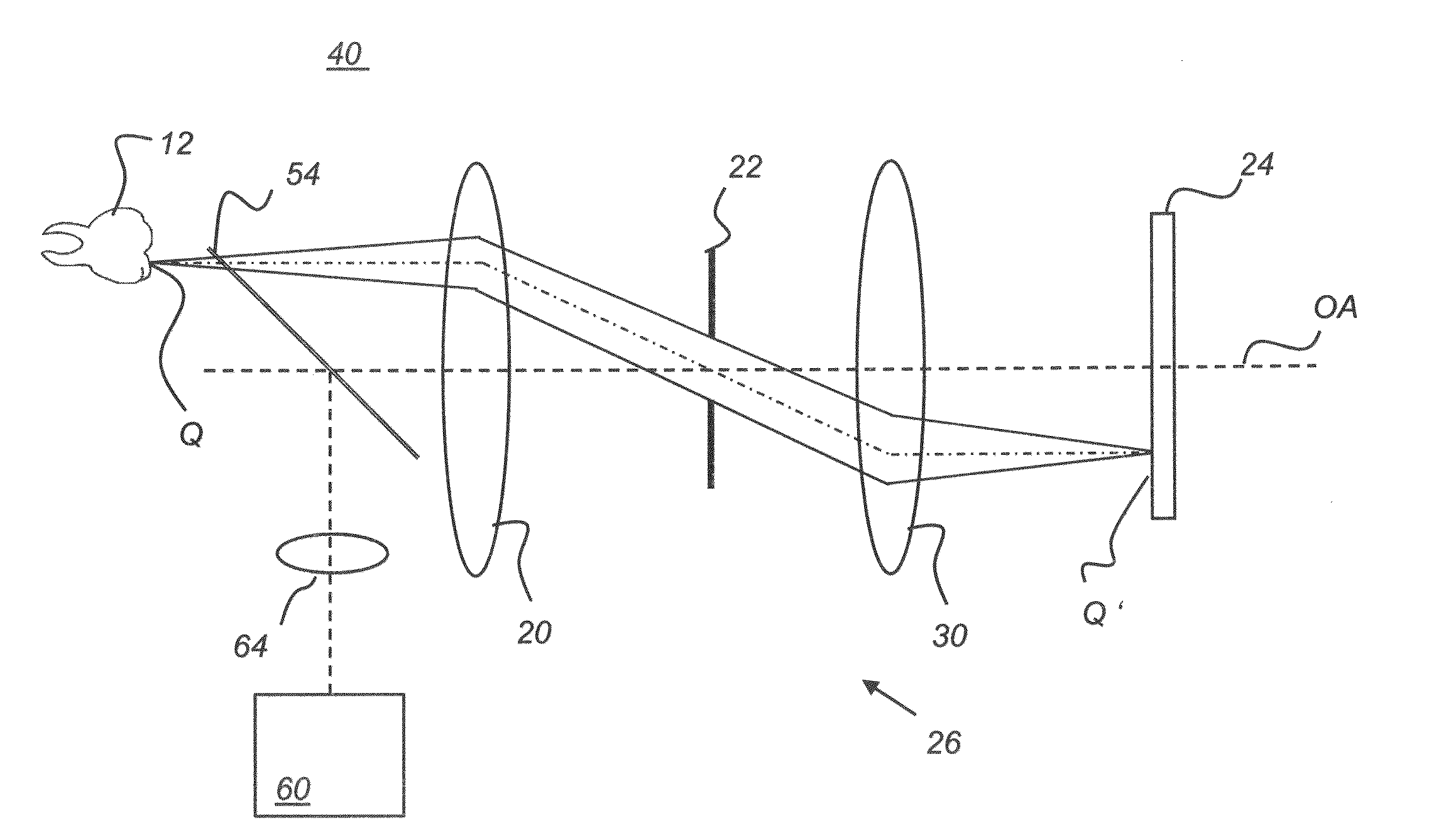
[0031]The apparatus and methods of the present invention obtain 3-D depth information from images by using telecentric defocus. In order to more fully understand the principles and operation of the present invention, it is instructive to review telecentricity in general and, more specifically, to describe the operation of the double telecentric optics of the apparatus of the present invention.

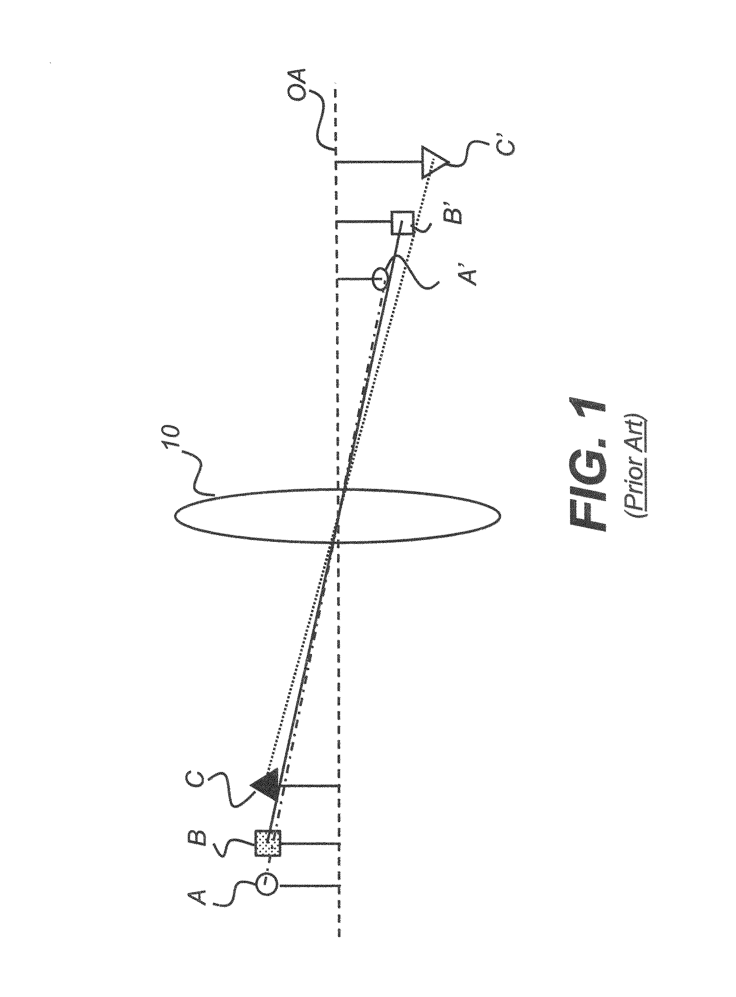
[0032]The schematic diagram of FIG. 1 shows how a lens 10 forms an image in a conventional, non-telecentric imaging system. In the object space to the left of lens 10, objects A, B, and C are all the same height. In image space, however, images A′, B′, and C′ are of different heights. Following this conventional model, the further the object is from the lens, t...


PUM


Abstract

An apparatus for obtaining 3-D surface contour image data of a tooth has a double telecentric optical system disposed to form an image of the surface of the tooth onto an image detector array. A focus adjustment mechanism is actuable to adjust the position of either or both the double telecentric optical system and the image detector array along an optical axis to each of a sequence of focus positions. A control logic processor is in control signal communication with the focus adjustment mechanism to adjust focus position, and is in image data communication with the image detector array for receiving image data obtained by the image detector array and with a memory for storing the received image data corresponding to each of the sequence of focus positions. The control logic processor is further responsive to stored instructions for computing 3-D surface contour image data from the image data.

Description

FIELD OF THE INVENTION[0001]The invention relates generally to the field of diagnostic imaging and in particular to 3-D imaging of intra-oral surfaces. More specifically, the invention relates to apparatus and methods for 3-D imaging using telecentric optics in a focus-changing sequence.BACKGROUND OF THE INVENTION[0002]The capability for 3-D imaging of teeth and intra-oral structures in general can help to improve dental care and diagnosis and to provide more accurate data for preparation of dental appliances and prosthetics. Although there have been a number of proposed solutions to this problem, inherent difficulties with each of these approaches limit their usability, accuracy, and cost-effectiveness.[0003]One conventional type of approach that has been proposed is contour or fringe projection imaging. Fringe projection imaging uses patterned or structured light to obtain surface contour information for complex structures of various types. In fringe projection imaging, a pattern ...

Claims


Application Information

Patent Timeline
IPC IPC(8): A61B6/14H04N7/18G06T17/00H04N13/02
CPCA61B5/1077A61B5/4547G01B11/25G01B11/24A61C9/0053A61C9/0066
Inventor LIANG, RONGGUANGRAY, LAWRENCE A.
Owner DENTAL IMAGING TECH
Why Eureka
Try Eureka