Automatic calibration error detection for ultrasonic inspection devices

an ultrasonic inspection and error detection technology, applied in the direction of instruments, structural/machine measurement, analysis of solids using sonic/ultrasonic/infrasonic waves, etc., can solve the problems of erroneous calibration, erroneous inspection, and acquisition of t2 of the ultrasonic inspection device, so as to improve the calibration productivity, avoid erroneous readings, and improve calibration efficiency

Active Publication Date: 2011-09-29
OLYMPUS AMERICA
View PDF1 Cites 12 Cited by
  • Summary
  • Abstract
  • Description
  • Claims
  • Application Information

AI Technical Summary

Benefits of technology

[0026]It also can be understood that the presently disclosed method for automatic calibration error detection provides the advantanges of improving calibration and therefore measurement / inspection confidence, accuracy and avoids erroneous readings.
[0027]It also can be understood that the presently disclosed method for automatic calibration error detection provides the advantanges of improving the calibrating productivity by eliminating time wasted in guessing whether the readings are valid, particularly if the UT device does not have a waveform display to verify (T2).

Problems solved by technology

However, it is quite frequent that the UT device acquires an erroneous T2 for the thin block an account of factors such as incorrect gain or signal noise.
The calibration would be therefore erroneous when an operator mistakenly accepts the erroneous T2.
This has been problematic particularly for inexperienced operators who might unknowingly perform erroneous calibrations, which subsequently produce erroneous inspections.
For experienced operators, erroneous readings slow down the calibration process, since the operator needs to stop and verify the calibration manually, which decreases productivity.
Moreover, if there is not a waveform display on the UT device to view the signal during the calibration session, the operator has no means to determine if T2 is correct.
However, the hardware solution is comparatively not cost effective and adaptable and suffers from instability with thermal drift.

Method used


Image

  • Automatic calibration error detection for ultrasonic inspection devices
  • Automatic calibration error detection for ultrasonic inspection devices
  • Automatic calibration error detection for ultrasonic inspection devices

Examples


Embodiment Construction

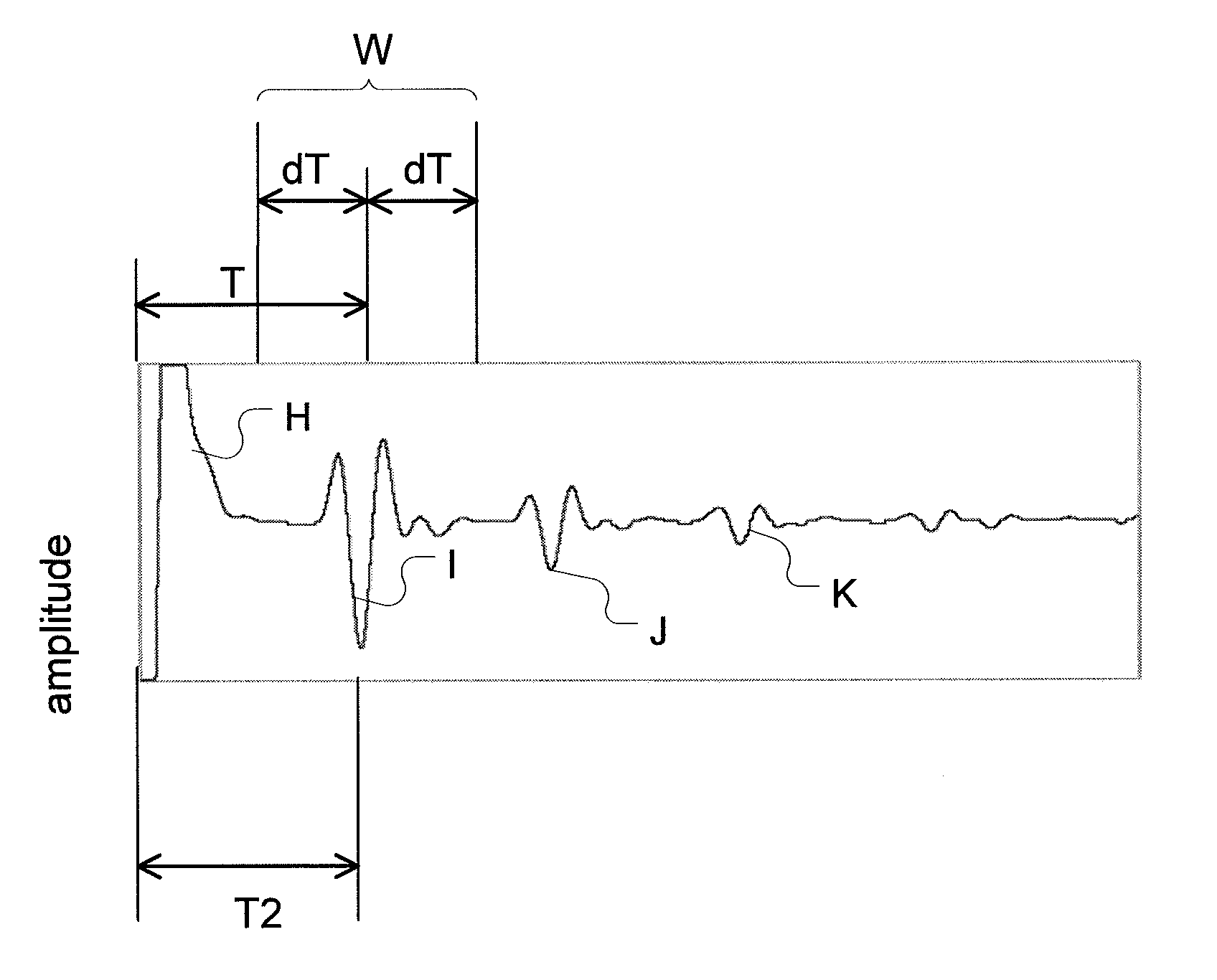
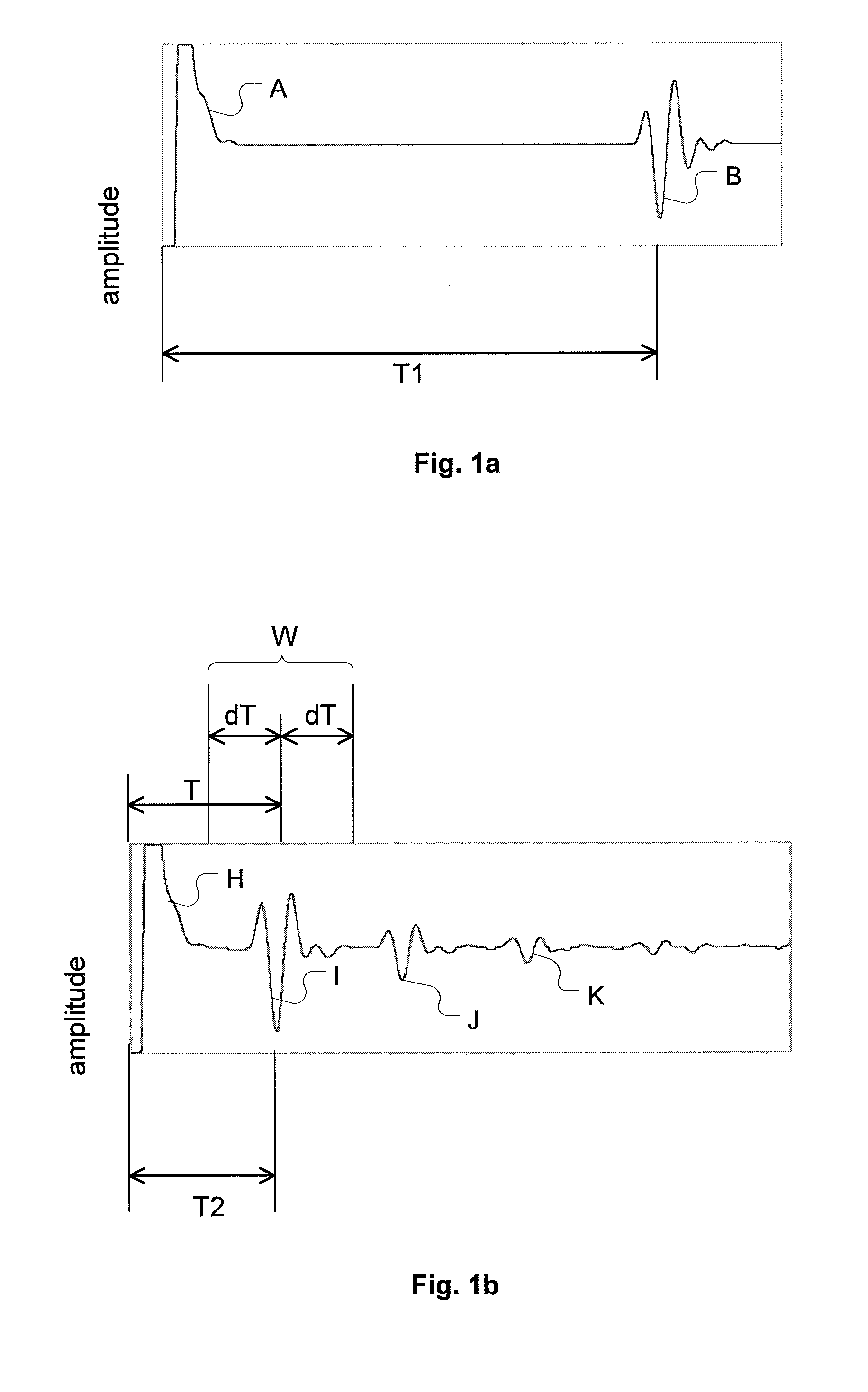
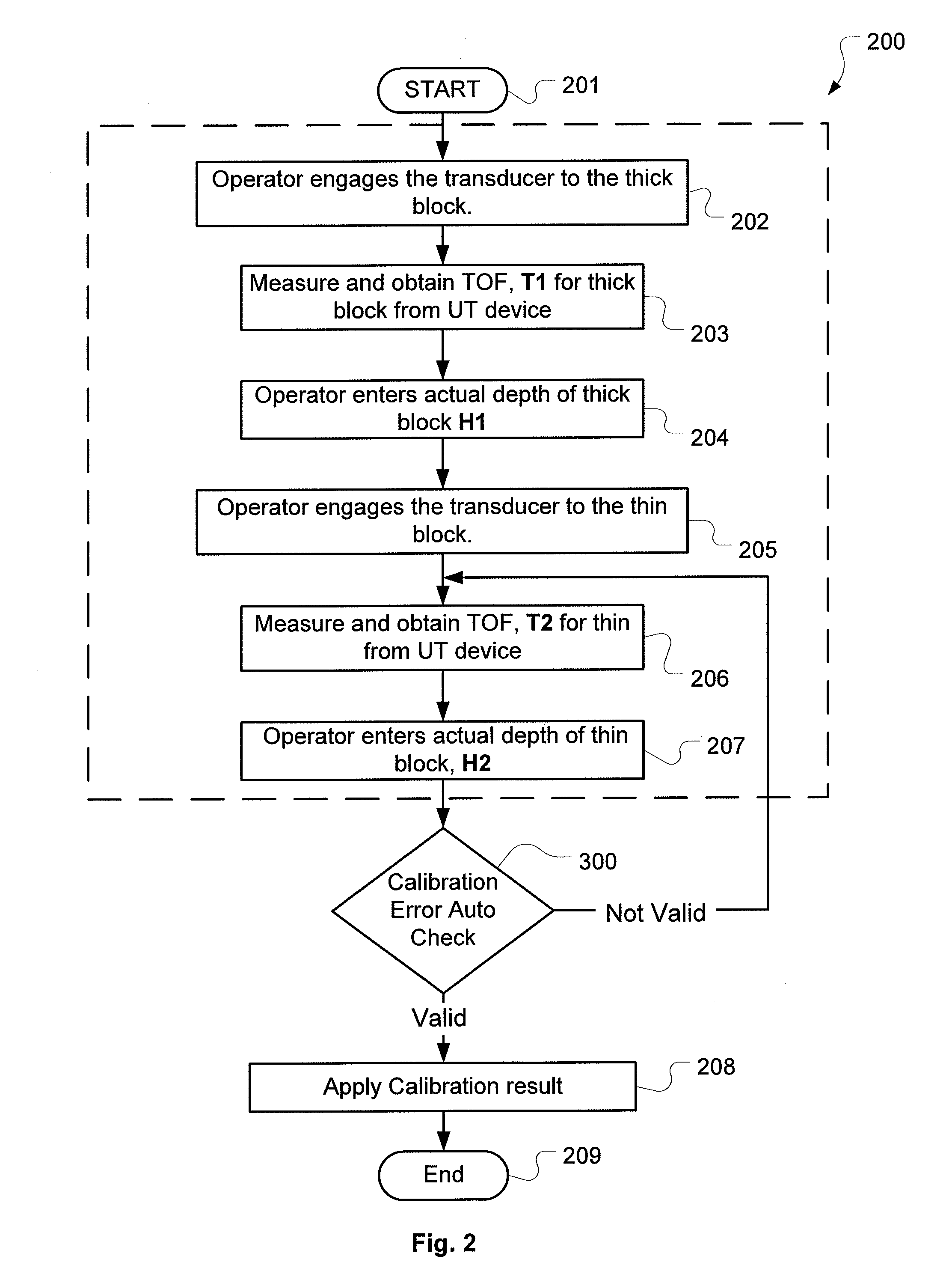
[0031]As described in the Background of the Invention, during a typical Two Point Calibration procedure, a transducer selected for calibration is engaged with a thick and then a thin block with known thickness (H1 and H2 respectively). The transducer is triggered and ultrasonic echo signals are captured by the UT device. Typical waveforms are plotted in FIGS. 1a and 1b.

[0032]Referring to FIGS. 1a and 1b, the ultrasonic waveforms reflected from the thick and the thin blocks are shown respectively. For both FIGS. 1a and 1b, the X-axis depicts the time required for the ultrasonic signals to travel to and be reflected from the backwall boundary of the testing objects, namely the thick block and the thin block. The Y-axis is the ultrasonic echo signal amplitude detected by the UT device.

[0033]In FIG. 1a, A represents the excitation pulse of the ultrasonic signal. B represents the first echo signal from the bottom boundary of the thick block which is detected by the UT device. T1 is the ...


PUM

PropertyMeasurementUnit
ultrasonicaaaaaaaaaa
thicknessaaaaaaaaaa
time-of-flightaaaaaaaaaa

Abstract

Disclosed is a method and an NDT/NDI calibration process that automatically detects erroneous TOF readings by providing a predetermined time acceptance window. During the calibration process, TOF readings acquired by a UT device are validated to determine whether the TOF reading for the thin test block falls within the range of the predetermined time acceptance window. If the TOF reading for the thin block (T2) falls out of the predetermined time acceptance window, the operator is alerted of an error and to repeat the TOF test for the thin block.

Description

CROSS REFERENCE TO RELATED APPLICATIONS[0001]This application claims priority under 35 U.S.C. §119(e) of U.S. Provisional Patent Application Ser. No. 61 / 317,446, filed Mar. 25, 2010, entitled “Automatic Calibration Error Detection for Ultrasonic Inspection Devices” (Attorney Docket No. PP / 4779-109). The complete contents of the priority application are hereby incorporated by their reference for all purposes.FIELD OF THE INVENTION[0002]The present invention relates to non-destructive testing and inspection devices (NDT / NDI) and more particularly to a method that automatically detects calibration data errors for ultrasonic inspection systems, such as thickness gauge devices.BACKGROUND OF THE INVENTION[0003]Ultrasonic apparatus calibration procedures fall into three categories, namely Transducer Zero Compensation, Material Velocity Calibration and Zero Offset Calibration. Presently, “Two Point Calibrations”, which is widely known in the art, utilizes the combination of “Zero Offset Cal...

Claims


Application Information

Patent Timeline
Patent Type & Authority Applications(United States)
IPC IPC(8): G01N29/30
CPCG01N29/07G01N29/4427G01N29/30
Inventor DEANGELO, PAUL JOSEPHLABRECK, STEVEN ABE
Owner OLYMPUS AMERICA
Why Eureka
Try Eureka