Pressure detecting device

a detection device and pressure technology, applied in measurement devices, oscillator generators, instruments, etc., can solve the problems of greatly affecting the measurement precision, and further lowering the precision of measuring a pressur

Inactive Publication Date: 2011-09-29
SEIKO EPSON CORP
View PDF6 Cites 18 Cited by
  • Summary
  • Abstract
  • Description
  • Claims
  • Application Information

AI Technical Summary

Benefits of technology

[0021]According to this configuration, since both the frequency-temperature characteristic of the resonator and the frequency-temperature characteristic of the AT-cut quartz crystal resonator can be compensated for, it is possible to improve the precision in measuring a pressure.
[0037]According to this configuration, it is possible to raise the frequency sensitivity to the pressure, thereby providing a high-precision pressure detecting device.

Problems solved by technology

However, in such a pressure sensor, the measurement precision is greatly affected by the frequency of the reference clock signal of the reference clock oscillator.
When an error exists in the reference clock signal, the counted value of the reference clock signal in the gate period departs from an appropriate value, thereby lowering the precision in measuring a pressure.
When the pressure is constant but the temperature varies, the frequency of the reference clock signal of the reference clock oscillator varies accordingly, thereby further lowering the precision in measuring a pressure.
For example, when the deviation in frequency of the reference clock signal of the TCXO due to the variation in temperature is ±1 ppm, the measurement error of the pressure sensor increases by ±2 Pa and the resultant measurement error is ±6 Pa.
Accordingly, the influence of the error of the reference clock signal on the pressure measuring precision increases.
Since the TCXO includes the temperature-compensating IC, there is a problem in that the power consumption in the temperature-compensating IC is high and the total power consumption of the pressure sensor is high accordingly.

Method used


Image

  • Pressure detecting device
  • Pressure detecting device
  • Pressure detecting device

Examples


first embodiment

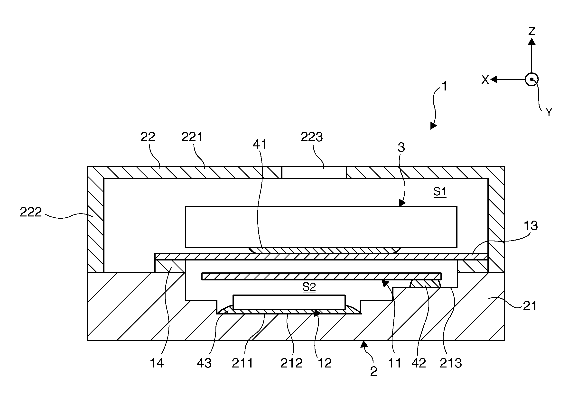
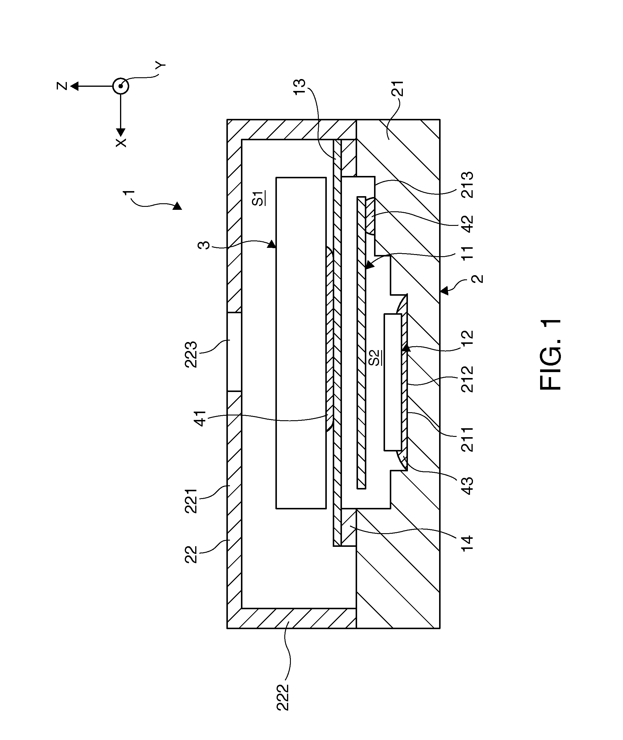
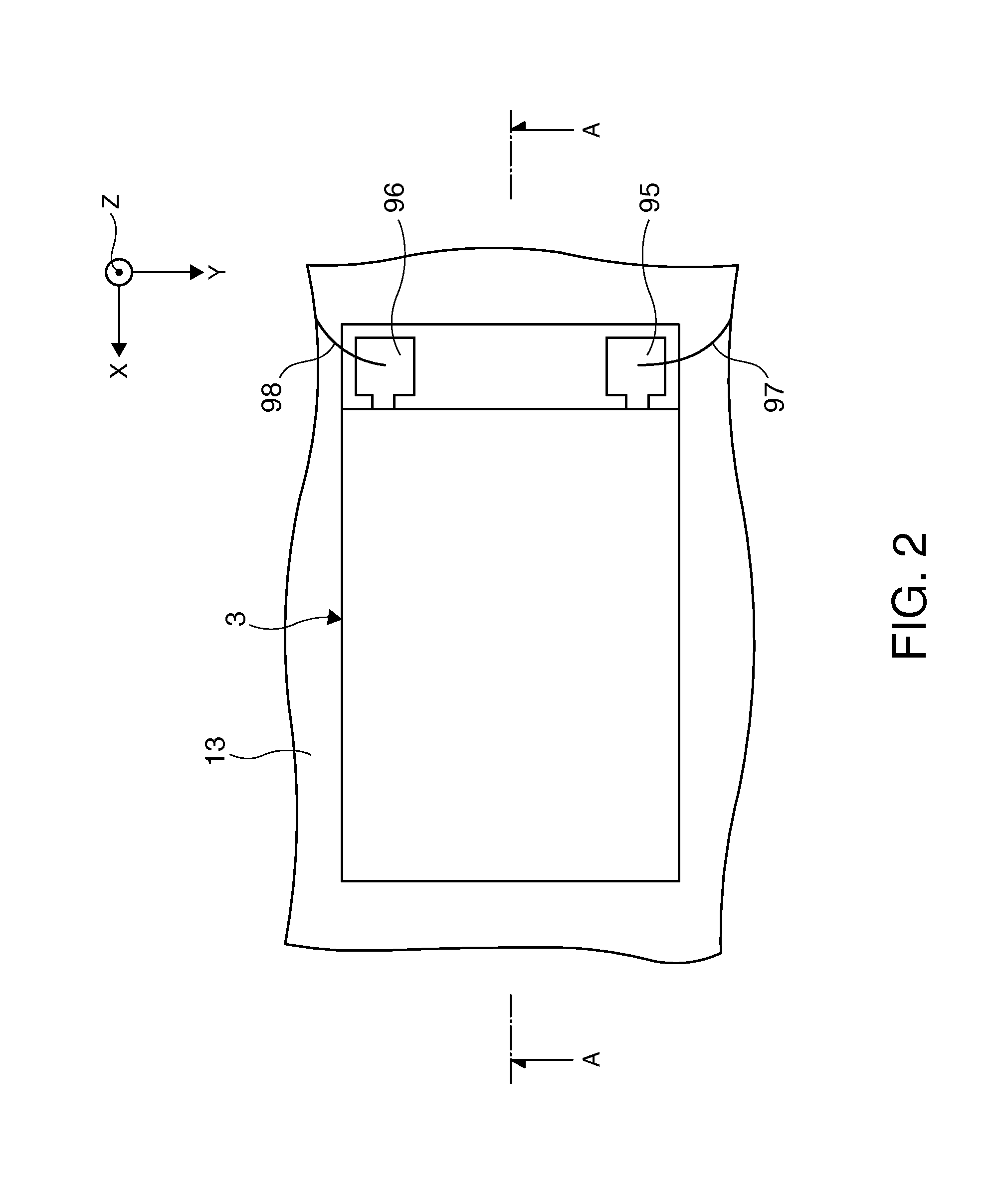
[0053]FIG. 1 is a sectional view illustrating a pressure sensor employing a pressure detecting device according to a first embodiment of the invention. FIG. 2 is a plan view illustrating a sensor chip of the pressure sensor shown in FIG. 1. FIG. 3 is a sectional view (a sectional view taken along line A-A of FIG. 2) of the sensor chip shown in FIG. 2. FIG. 4 is a plan view illustrating a piezoelectric vibration element layer of the sensor chip shown in FIG. 3. FIGS. 5A to 5D are perspective views illustrating a double-ended tuning fork type piezoelectric vibration element of the sensor chip shown in FIG. 3. FIGS. 6A and 6B are sectional views illustrating the behavior of the sensor chip. FIG. 7 is a block diagram illustrating the circuit configuration of the pressure sensor shown in FIG. 1. FIG. 8 is a timing diagram illustrating a reciprocal counting method in the pressure sensor shown in FIG. 1. FIGS. 9A to 9E are graphs illustrating the correction of a count value of a reference ...

second embodiment

[0161]FIG. 12 is a sectional diagram illustrating a pressure sensor employing a pressure detecting device according to a second embodiment of the invention.

[0162]The differences of the second embodiment from the above-mentioned first embodiment will be mainly described below and the same elements or configurations will not be described.

[0163]As shown in FIG. 12, in the pressure sensor 1 according to the second embodiment, a concave portion 211 is formed at the center of the bottom of the base 21.

[0164]The lid (cover member) 15 is bonded to a third-stage portion 213 from the bottom of the concave portion 211 of the base 21 with the seam ring 16 interposed therebetween and the opening of the concave portion 211 is covered with the lid 15. Accordingly, a space (cavity) S4 surrounded with the lid 15, the seam ring 16, and the inner walls of the base 21 is formed.

[0165]Similarly to the space S2 in the first embodiment, the space S4 is closed, that is, air-tightly sealed. It is preferable...

third embodiment

[0171]FIG. 13 is a sectional diagram illustrating a pressure sensor employing a pressure detecting device according to a third embodiment of the invention.

[0172]The differences of the third embodiment from the above-mentioned first embodiment will be mainly described below and the same elements or configurations will not be described.

[0173]As shown in FIG. 13, a pressure (pressing force) sensor 1b according to the third embodiment includes a pressure sensor body 10b and a package (second package) 20 receiving the pressure sensor body 10b therein.

[0174]The structure of the pressure sensor body 10b is the same as the structure of the pressure sensor 1 according to the first embodiment. The control is different, in that the pressure sensor 1 measures an atmospheric pressure but the pressure sensor body 10b finally measures a force (pressing force) applied to the package 20.

[0175]The package 20 includes a base (body) 201 and a deformable lid (cover member) 202 which are bonded to each o...


PUM

PropertyMeasurementUnit
oscillation frequencyaaaaaaaaaa
pressureaaaaaaaaaa
frequencyaaaaaaaaaa

Abstract

A pressure detecting device includes: a resonator whose oscillation frequency varies depending on a pressure; a first oscillation circuit that oscillates the resonator and outputs a signal of a frequency corresponding to the pressure; an AT-cut quartz crystal resonator; a second oscillation circuit that oscillates the AT-cut quartz crystal resonator and outputs a reference clock signal; a measuring unit that measures the reference clock signal by the use of a reciprocal counting method; a temperature detecting unit that detects a temperature of the resonator; and a storage unit that stores coefficients of a first approximating polynomial for calculating a first correction value used to compensate for a frequency-temperature characteristic of the measuring unit, wherein the frequency-temperature characteristic of the value measured by the measuring unit includes a frequency-temperature characteristic of the AT-cut quartz crystal resonator and a frequency-temperature characteristic of the resonator.

Description

BACKGROUND[0001]1. Technical Field[0002]The present invention relates to a pressure detecting device.[0003]2. Related Art[0004]JP-A-2007-327922 discloses a pressure sensor including a diaphragm, a container, and a double-ended tuning fork type resonator (pressure-sensitive element) mounted on a support portion of the diaphragm.[0005]In such a pressure sensor, a flexible diaphragm is deformed with a pressure applied to a pressure-receiving face, tensile stress (extensional stress) or compressive stress is applied to two vibration beams of a double-ended tuning fork type resonator, and the magnitude of the pressure applied to the pressure sensor is detected by measuring the oscillation frequency (resonance frequency) of the double-ended tuning fork type resonator which varies depending on the tensile stress or the compressive stress.[0006]In the pressure sensor, when a double-ended tuning fork type resonator using quartz crystal as a base material is used as a pressure-sensitive eleme...

Claims


Application Information

Patent Timeline
Patent Type & Authority Applications(United States)
IPC IPC(8): G01L11/00
CPCG01L9/008G01L9/0022
Inventor SAKURAI, TOSHINOBU
Owner SEIKO EPSON CORP
Why Eureka
Try Eureka