
Non-evaporable getter for field-emission display

a field-emission display and vaporizer technology, applied in vacuum obtaining/maintenance, transportation and packaging, gas-filled discharge tubes, etc., can solve the problems of large and heavy crt, degrading the performance of the electron source due to gas, and difficulty in sufficiently removing remaining gas in the container, etc., to achieve high absorbing speed

Inactive Publication Date: 2011-09-29
CANON KK
View PDF7 Cites 7 Cited by
  • Summary
  • Abstract
  • Description
  • Claims
  • Application Information

AI Technical Summary

Benefits of technology

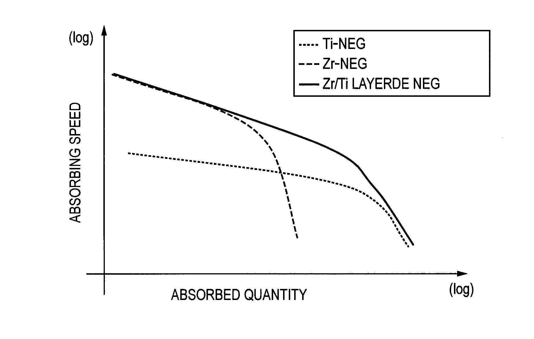
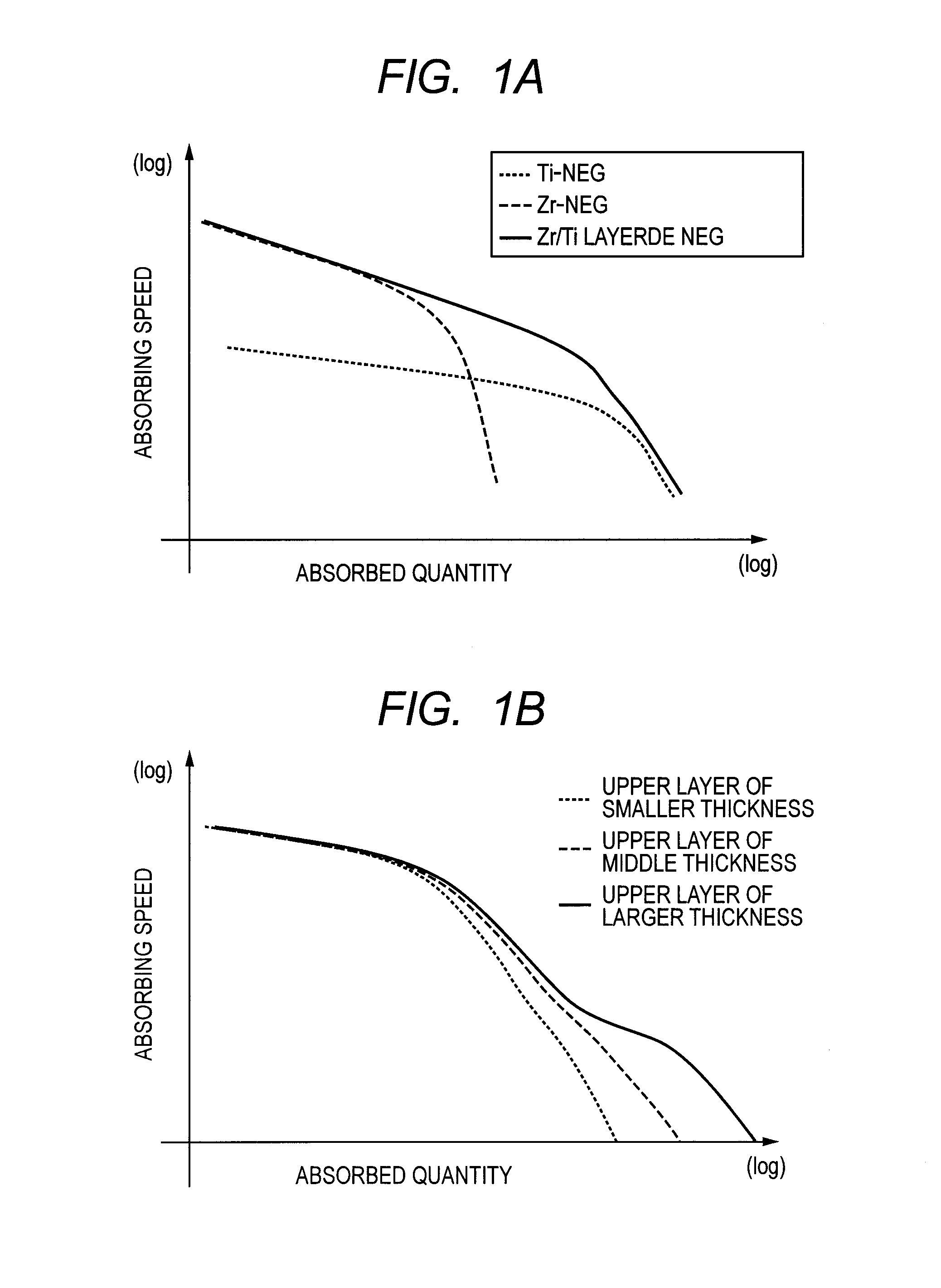
[0018]An object of the present application is to provide a non-evaporable getter suitable for removing plural types of desorption gas and remaining gas from the container constituting the FED. Particularly, one object of the present application is to provide a non-evaporable getter which shows a high absorbing speed for H2O gas in the early stage of activation, and keeps an absorbing speed for CO gas for a long period of time. The present invention also includes a method for manufacturing such a non-evaporable getter and an FED provided with the non-evaporable getter, in its scope.

Problems solved by technology

However, there is a problem that the CRT is large and heavy, and a light thin tabular image display apparatus which is so-called a flat panel display (Flat Panel Display: hereafter referred to as FPD) has received attention as a substitute for the CRT.
This is because if the pressure in the container increases, there arise such problems that the performance of the electron source degrades due to gas, the electron source is destroyed by an ionized gas, and the electron source and the container are destroyed by electric discharge.
However, it is difficult to sufficiently remove remaining gases in the container only by this method, and it is impossible to remove the desorption gas which is formed when elements in the container have been driven after the container has been sealed.
On the other hand, because the getter cannot be exposed to the atmosphere after having been vapor-deposited once, it is necessary to consistently perform steps from the vapor deposition of the getter to the sealing of the container, in a vacuum.
However, the non-evaporable getter shows low absorption capability for CO gas, and as for the CO gas, the absorption capability is insufficient for the stable drive of the FED.
In addition, a non-evaporable getter containing Ti as a main component has a sufficiently high absorption capability for the CO gas, but has an insufficient absorption capability for the H2O gas.
Thus, the FED has a problem that it is difficult to sufficiently remove the gases in the inner part of the container of the FED by a getter formed of a film having a single composition, because a plurality of gases which should be removed out from the container exist therein.

Method used


Image

  • Non-evaporable getter for field-emission display
  • Non-evaporable getter for field-emission display
  • Non-evaporable getter for field-emission display

Examples


exemplary embodiment 1

[0084]A Ti layer was film-formed on a glass substrate having the thickness of 1.8 mm with a sputtering method. Then, a Zr layer was subsequently film-formed on the Ti layer with the sputtering method, without exposing the Ti layer to the air. The film forming conditions are shown in the following Table 1.

exemplary embodiment 2

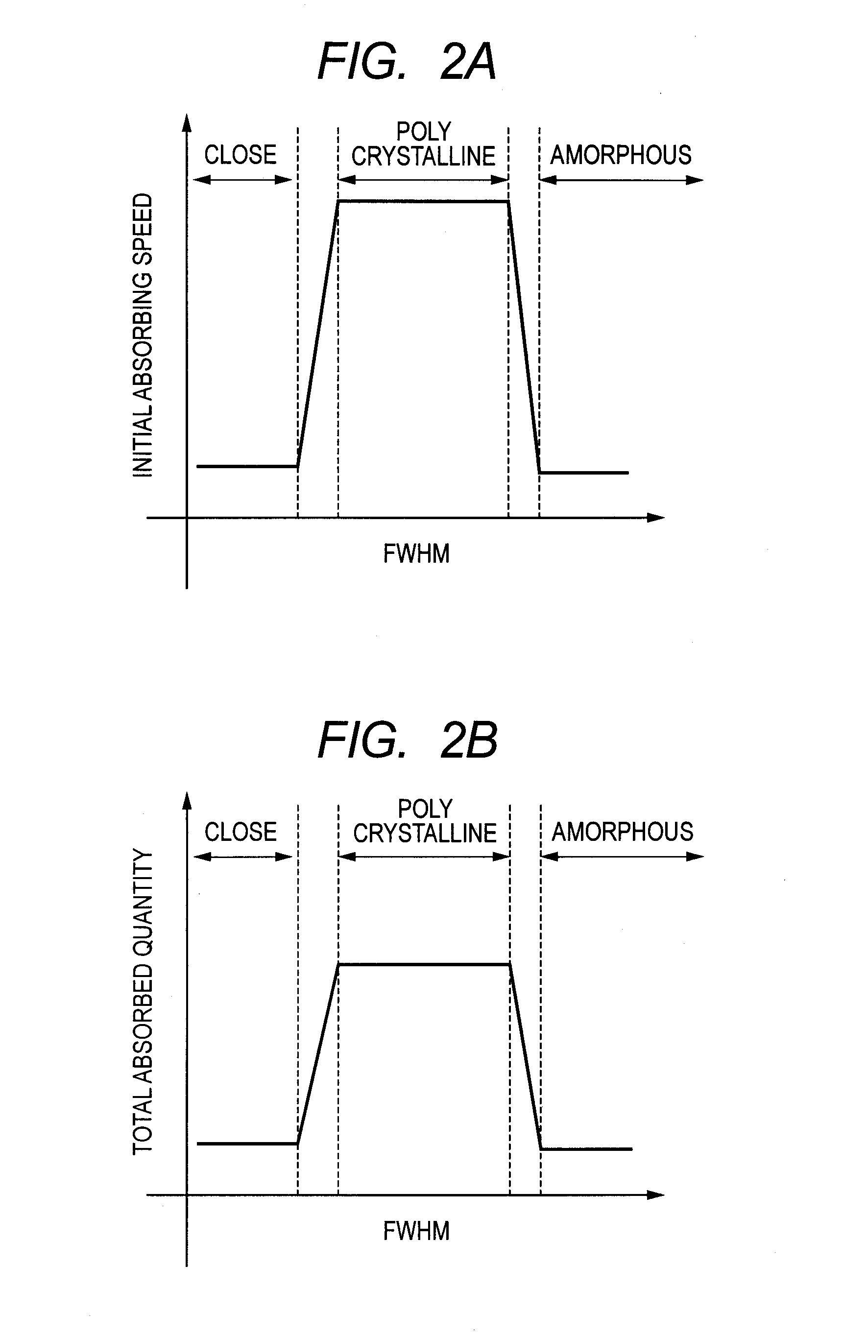
[0089]A Ti layer was film-formed on a glass substrate having the thickness of 1.8 mm with a sputtering method. Then, a Zr layer was subsequently film-formed on the Ti layer with the sputtering method, without exposing the Ti layer to the air. The film forming conditions for the Zr layer were selected so that the Zr crystal was polycrystalline. The film forming conditions in Exemplary Embodiment 2 are shown in the following Table 2. As a result of a crystalline analysis by XRD of the produced non-evaporable getter, the FWHM of the peak corresponding to the plane (100) was 1.2°.

exemplary embodiment 3

[0095]A Ti layer was film-formed on a glass substrate having the thickness of 1.8 mm with a sputtering method.

[0096]Then, a Zr layer was subsequently film-formed on the Ti layer with the sputtering method, without exposing the Ti layer to the air. The film forming conditions for the Zr layer were selected so that a polycrystalline Zr layer was formed. The film forming conditions are shown in the following Table 3.


PUM

PropertyMeasurementUnit
Grain sizeaaaaaaaaaa
Thicknessaaaaaaaaaa
Angleaaaaaaaaaa

Abstract

The present invention provides a non-evaporable getter for an FED which can remove a plurality of types of gases. The non-evaporable getter for the FED has a first layer containing titanium, and a second layer containing crystalline zirconium layered on the first layer. The average value of crystalline grain sizes of the crystalline zirconium is 3 nm or more but 20 nm or less.

Description

BACKGROUND OF THE INVENTION[0001]1. Field of the Invention[0002]The present invention relates to a non-evaporable getter for a field-emission display, which can absorb a gas, and a manufacturing method therefor.[0003]2. Related Background Art[0004]In recent years, an image area of an image display apparatus has progressively become larger. Conventionally, a cathode ray tube (Cathode Ray Tube: hereafter referred to as CRT) has been most popularly used as the image display apparatus. However, there is a problem that the CRT is large and heavy, and a light thin tabular image display apparatus which is so-called a flat panel display (Flat Panel Display: hereafter referred to as FPD) has received attention as a substitute for the CRT.[0005]In these years, the FPD has been actively researched and developed, and FPDs based on various principles such as a liquid crystal display device, a plasma display and an organic EL have been developed. As one of such field-emission displays, there is a...

Claims


Application Information

Patent Timeline
IPC IPC(8): H01J17/24B05D1/36B32B15/04H01J29/94
CPCH01J29/94Y10T428/12812H01J2329/948H01J31/127
Inventor YOSHITAKE, TADAYUKIMORIGUCHI, TAKUTOANDO, YOICHI
Owner CANON KK
Learn More